Inner Tension Hollow Cylinder Fixture

A hollow cylinder, internal tension technology, applied in the direction of clamping, manufacturing tools, metal processing machinery parts, etc., can solve the problem of easy detachment of the cylinder, loosening of the cylinder, reduction of the friction block and the clamping force of the cylinder, etc. Problems, achieve good clamping effect, easy loosening, stable and powerful clamping effect

Active Publication Date: 2020-05-19
SUZHOU GUANGXING MOLD
View PDF11 Cites 0 Cited by
  • Summary
  • Abstract
  • Description
  • Claims
  • Application Information

AI Technical Summary

Problems solved by technology

[0002] During the workpiece cutting process, due to the gravity of the cylinder, machining vibration, workpiece movement, temperature rise, etc., the clamped part of the cylinder is prone to deformation, which leads to a decrease in the clamping force between the friction block and the cylinder, and the cylinder The body is easy to break away from the grip of the fixture, and the cylinder is loose, resulting in poor machining accuracy or safety accidents

Method used


Image

  • Inner Tension Hollow Cylinder Fixture
  • Inner Tension Hollow Cylinder Fixture
  • Inner Tension Hollow Cylinder Fixture

Examples


Embodiment 1

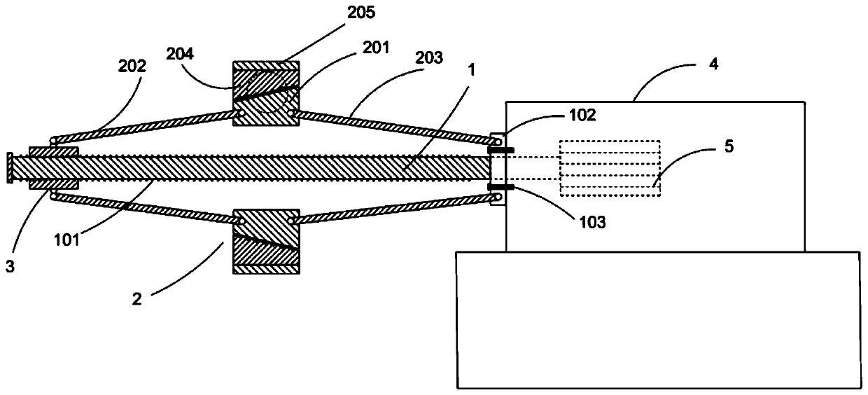
[0026] Such as figure 1 , 2 As shown, an internally tensioned hollow cylinder clamp is characterized in that it includes: a main shaft 1, a fastener 2, a looper 3, and the looper 3 is provided with an internal thread, and is socketed on one side of the main shaft 1;

[0027] The main shaft 1 is provided with an external thread 101 that matches the internal thread of the looper 3, and a fixed disk 102 is vertically provided on the main shaft 1 relative to one end of the looper 3;

[0028] The fastener 2 includes a connecting rod and a fastening head 201. The connecting rod includes a first connecting rod 203 and a second connecting rod 202. One end of the first connecting rod 203 is hinged to the fastening head 201, and the other end is connected to the fastening head 201. The fixed disc 102 is hingedly connected; one end of the second connecting rod 202 is hingedly connected with the fastening head 201, and the other end is hingedly connected with the looper 3. The longitudin...

Embodiment 2

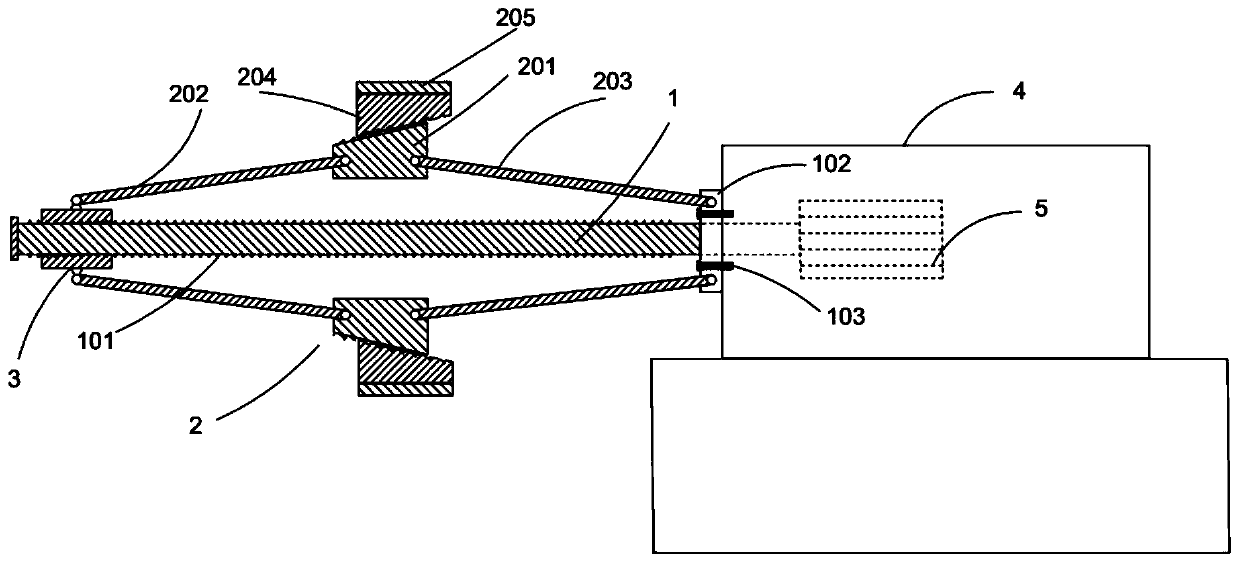
[0039] Such as image 3 As shown, when the main shaft 1 rotates clockwise, the looper 3 approaches the fixed plate 102 along the thread, the fastening head 201 is lifted, and the cylinder or hollow workpiece is clamped from the inside; the main shaft 1 rotates counterclockwise When rotating in the same direction, the looper 3 moves away from the fixed disk 102 along the thread, the fastening head 201 descends, and the workpiece is loosened.

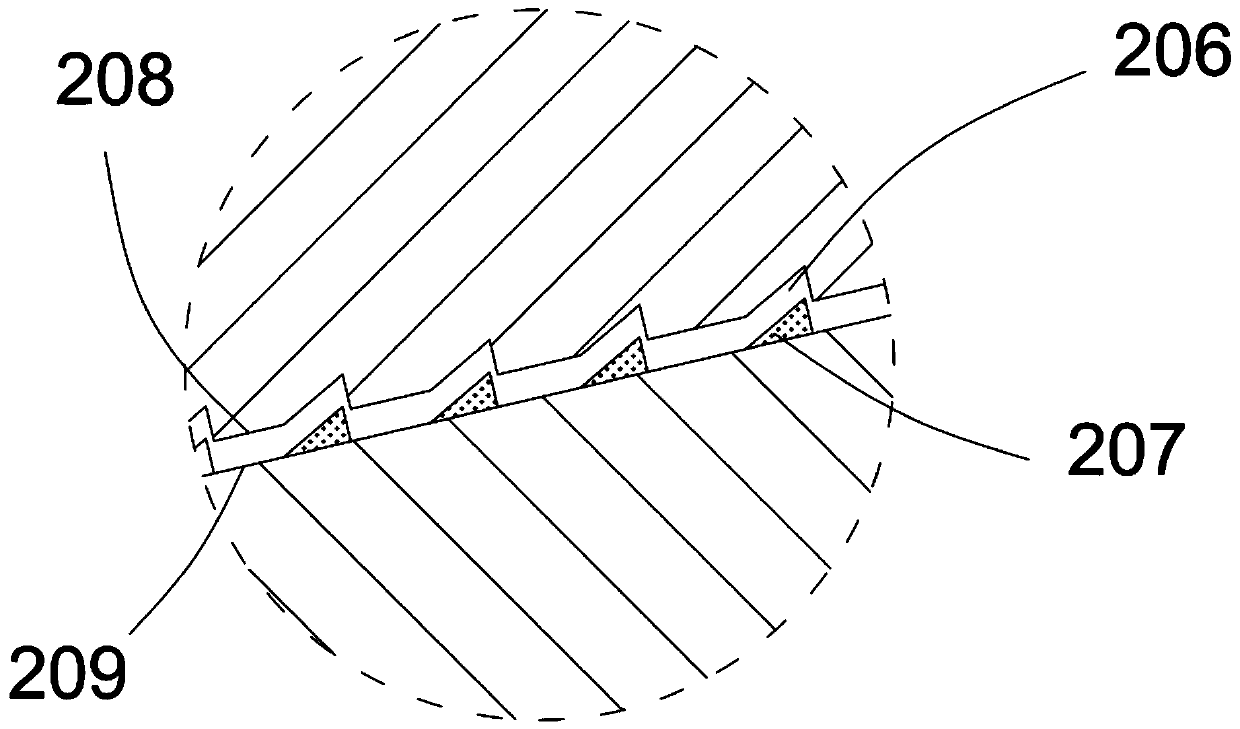
[0040] During the workpiece cutting process, due to the gravity of the workpiece, machining vibration, workpiece movement, temperature rise, etc., the clamped part of the workpiece is loose or deformed. At this time, the friction provided by the fastening plate 204 on the sulfur-free hard rubber layer 205 Move with the workpiece under force, so that the fastening plate 204 slides in one direction along the first inclined surface 209 to the direction close to the fastening plate 102, and the overall thickness of the fastening head 201 and ...


PUM


Abstract

The invention relates to an internal expansion type hollow cylindrical fixture. The internal expansion type hollow cylindrical fixture comprises a main shaft, fastening parts and a movable sleeve; aninner thread is formed in the movable sleeve, and the movable sleeve is connected to one side of the main shaft in a sleeving mode; the main shaft is overall provided with an outer thread matched withthe inner sleeve of the movable sleeve, and a fixing disc is perpendicularly arranged at the end, opposite to the movable sleeve, of the main shaft; each fastening part comprises a connecting rod anda fastening head, and each connecting rod comprises a first connecting rod and a second connecting rod; one end of each first connecting rod is in hinged shaft connection with the corresponding fastening head, and the other end of each first connecting rod is in hinged shaft connection with the fixing disc; and one end of each second connecting rod is in hinged shaft connection with the corresponding fastening head, and the other end of each second connecting rod is in hinged shaft connection with the movable sleeve. According to the internal expansion type hollow cylindrical fixture, clamping is stable and powerful, disengaging is convenient, and the internal expansion type hollow cylindrical fixture can be self-adaptive to small deformation in the workpiece machining process and has thegood clamping effect on hollow cylinders and pipes with different sizes and shapes.

Description

technical field [0001] The invention belongs to the field of metal cutting processing fixtures, in particular to an internal tension type hollow cylinder fixture. Background technique [0002] During the workpiece cutting process, due to the gravity of the cylinder, machining vibration, workpiece movement, temperature rise, etc., the clamped part of the cylinder is prone to deformation, which leads to a decrease in the clamping force between the friction block and the cylinder, and the cylinder The body is easy to break away from the grip of the fixture, and the cylinder body is loose, resulting in poor machining accuracy or safety accidents. Contents of the invention [0003] The object of the present invention is to provide an internally stretched hollow cylinder clamp capable of stably clamping workpieces. [0004] Another object of the present invention is to provide an internally tensioned hollow cylinder fixture that can adapt to the small deformation of the workpie...

Claims


Application Information

Patent Timeline
Patent Type & Authority Patents(China)
IPC IPC(8): B23Q3/06
CPCB23Q3/06
Inventor 马广兴
Owner SUZHOU GUANGXING MOLD
Why Eureka
Try Eureka