Food processor with tools combined to a tool unit

A technology of food processor and tool unit, which is applied in home appliances, kitchen appliances, applications, etc. It can solve the problems of large storage space, difficulty in use, and complexity, and achieve good protection and prevent accidental disappearance or loss.

Inactive Publication Date: 2009-09-23
KONINKLIJKE PHILIPS ELECTRONICS NV
View PDF5 Cites 0 Cited by
  • Summary
  • Abstract
  • Description
  • Claims
  • Application Information

AI Technical Summary

Problems solved by technology

In addition to this rather complicated and awkward handling, this known food processor also has the problem of requiring a relatively large storage space for the various tools, and those tools which were not selected at the time also need to be combined with other tools. Separate storage space for food processor

Method used


Image

  • Food processor with tools combined to a tool unit
  • Food processor with tools combined to a tool unit
  • Food processor with tools combined to a tool unit

Examples


Embodiment Construction

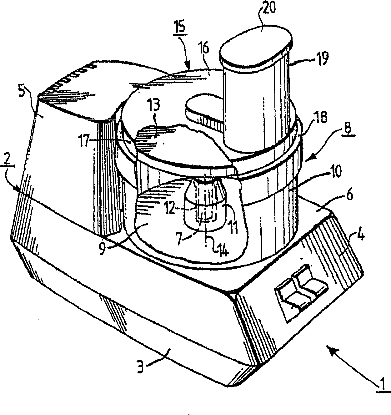
[0022] figure 1 A food processor 1 is shown. This food processor 1 is designed for processing food. For example, this food processor can be used to chop vegetables into thick or thin strips, or they can be grated through the grate into small pieces. Also, vegetables can be sliced ​​thinly.

[0023] The food processor 1 is equipped with a housing 2 comprising a trough-shaped bottom 3 and an inverted trough-shaped top 4 from which tower-shaped sides 5 protrude. The drives for the tools for operating the food processor and the power circuits for the drives are housed in the housing area comprising the bottom 3 and the top 4 . The drive unit is equipped with an electric motor and a transmission that can be driven by the motor, however they are figure 1 is not shown in . The reason is that the specific design of the drive is not important in this case. The drive shaft 7 passing from the drive through the cover wall 6 of the top 4 is in the figure 1 visible in .

[0024] The...


PUM


Abstract

A drivable holder (13) for a tool unit (29) is provided in a food processor (1), the tool unit (29) being equipped with a plurality of tools (26, 27, 28) and capable of holding The frame (13) is repositioned so as to enable one tool (26) from the tool unit (29) to be placed in the area of ​​the window (25) in the cage wall (21) of the cage (13) at a time position, while the other tools (27, 28) are thus covered by the cage wall (21).

Description

technical field [0001] The invention relates to a food processor, which is equipped with at least two tools for processing food, and which comprises a drive for driving these tools, and which comprises Holder for holding the tools, the holder can be driven by a driving device, the holder is equipped with a holder wall, and the holder has a window in the holder wall, the tools held by the holder can be moved one at a time placed in the window. Background technique [0002] Such a food processor according to the design cited in the first paragraph above is disclosed in patent document US 4 190 208 A and is thus known. In the case of this known food processor, the design is such that one of the tools can be connected as required to a substantially disc-shaped holder for holding these tools by using the provided wedge The tenon connection is achieved by inserting the selected specific tool radially into the cage so that the selected specific tool is received and positioned in ...

Claims


Application Information

Patent Timeline
Patent Type & Authority Patents(China)
IPC IPC(8): A47J43/25A47J43/07
CPCA47J43/0722
Inventor H·奥伯斯泰纳
Owner KONINKLIJKE PHILIPS ELECTRONICS NV
Why Eureka
Try Eureka