
Air suction and blow cleaning device used in spinning frame

A cleaning device and air suction technology, which is applied in the direction of textiles and papermaking, can solve the problems of inability to clean roving slopes, high labor costs, low production quality and production efficiency, and achieve labor cost savings, improved production quality and production efficiency, The effect of reasonable structural design

Pending Publication Date: 2018-12-07
SHANDONG HUAXING TEXTILE GROUP
View PDF8 Cites 0 Cited by
  • Summary
  • Abstract
  • Description
  • Claims
  • Application Information

AI Technical Summary

Problems solved by technology

[0004] The technical task of the present invention is to address the above deficiencies, to provide a blowing and blowing cleaning device for spinning frames, which can solve the problem that the position of the nozzle of the traditional blowing and suction cleaning device in the prior art is on the upper side, and the inclined blowing nozzle can only blow the most The outer row of roving slopes cannot clean the inner roving slopes, and manual cleaning is used, which has the problems of high labor costs, low production quality and production efficiency

Method used


Image

  • Air suction and blow cleaning device used in spinning frame
  • Air suction and blow cleaning device used in spinning frame

Examples


Embodiment 1

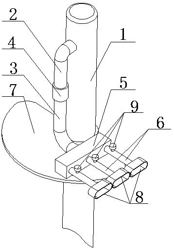
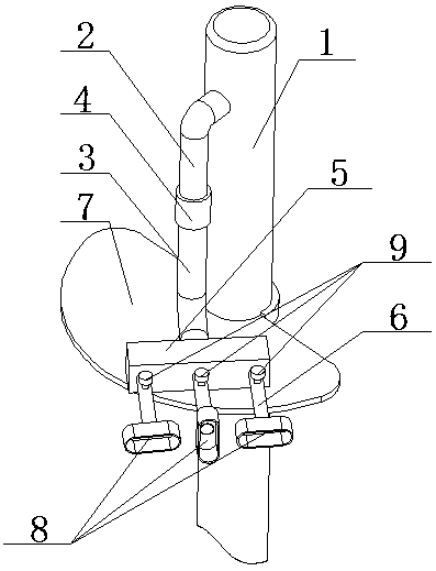
[0026] A blowing suction cleaning device for spinning frame of the present invention comprises blowing pipe 1 and blowing nozzle 2, blowing nozzle 2 is arranged on the outer wall of blowing pipe 1; the lower end of blowing nozzle 2 is provided with corrugated hose 3, blowing nozzle 2 There is a rotary sealing joint 4 between the corrugated hose 3, which is used for the corrugated hose 3 to rotate around the blowing nozzle 2; the lower end of the corrugated hose 3 is connected to the shunt bellows 5, and the other end of the shunt bellows 5 is connected to three air outlet pipes 6, The air outlet of the air outlet pipe 6 is movably provided with a nozzle 8 in the shape of a straight notch, and the nozzle 8 can rotate around the air outlet pipe 6; each air outlet pipe 6 is provided with a throttle valve 9 for controlling the outlet of the nozzle 8. The size of the air volume; the fan-shaped support frame 7 is movably socketed on the outer wall of the blowing pipe 1, and the split...


PUM


Abstract

The invention discloses an air suction and blow cleaning device used in a spinning frame, and belongs to the technical field of cotton textile machinery. The device aims at solving technical problemsthat a blow nozzle of a traditional air suction and blow cleaning device in the prior art is arranged at the upper portion, the inclined blow nozzle only can blow roving slopes in the outermost row but cannot clean roving slopes on the inner side, and manual cleaning has the problems of high labor cost, low production quality and low production efficiency. According to the technical scheme, the device comprises a blow pipe and a blow nozzle, and the blow nozzle is arranged on the outer wall of the blow pipe; a corrugated hose is arranged at the lower end of the blow nozzle, and a rotary seal connector is arranged between the blow nozzle and the corrugated hose and used for enabling the corrugated hose to rotate around the blow nozzle; the lower end of the corrugated hose is connected witha distribution bellows, and the other end of the distribution bellows is connected with a plurality of air outlet pipes.

Description

technical field [0001] The invention relates to the technical field of cotton textile machinery, in particular to a suction blow cleaning device used on spinning frames. Background technique [0002] The spinning frame is the main machine for spinning. The spinning frame is a spinning machine that draws, twists, and winds the semi-finished roving or sliver into a spun bobbin during the spinning process. The output and quality of the spun yarn are determined by the spinning process. A comprehensive reflection of the pros and cons of the process. The production unit of the spinning frame is the spindle, and the production level of the spinning frame is often measured by the output per thousand spindle hours. The production scale of the spinning mill is expressed by the total number of spindles owned by the spinning frame. The yarn spun on each spindle will be broken due to various reasons, and the rate of broken ends will affect labor productivity, equipment productivity, sp...

Claims


Application Information

Patent Timeline
Patent Type & Authority Applications(China)
IPC IPC(8): D01H11/00
CPCD01H11/006
Inventor 潘广周方安宁吴刚
Owner SHANDONG HUAXING TEXTILE GROUP
Learn More