Opened door self-locking type door stopper

A door suction and self-locking technology, which is applied in the direction of construction, building fastening devices, wing leaf fastening devices, etc., can solve the problems of unreliable door leaf positioning, high cost, complex structure, etc., and achieve simple structure, The effect of low cost and high reliability

Active Publication Date: 2018-12-07
常州联企知识产权代理有限公司
View PDF8 Cites 1 Cited by
  • Summary
  • Abstract
  • Description
  • Claims
  • Application Information

AI Technical Summary

Problems solved by technology

[0003] The technical problem to be solved by the present invention is: in order to solve the problem of unreliable positioning effect of the magnetic door stopper on the door leaf in the prior art, its complex structure and high cost, a self-locking door stopper for opening the door is now provided, which is applicable outdoor patio door

Method used


Image

  • Opened door self-locking type door stopper
  • Opened door self-locking type door stopper
  • Opened door self-locking type door stopper

Examples


Embodiment 1

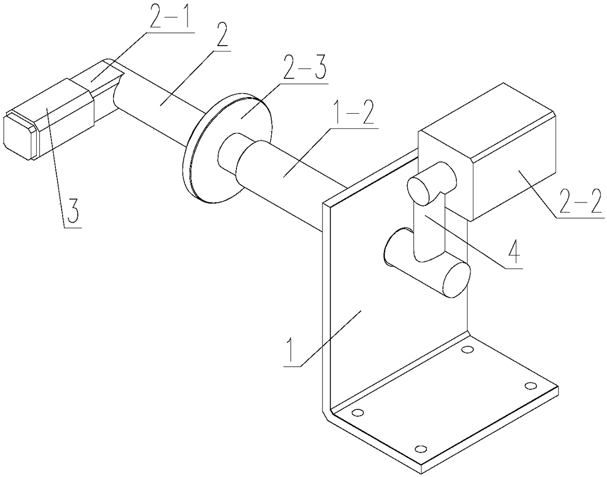
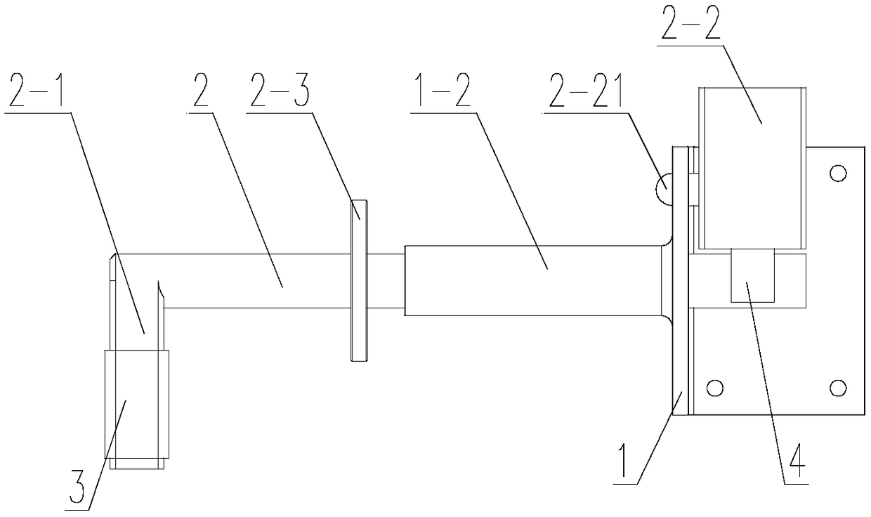
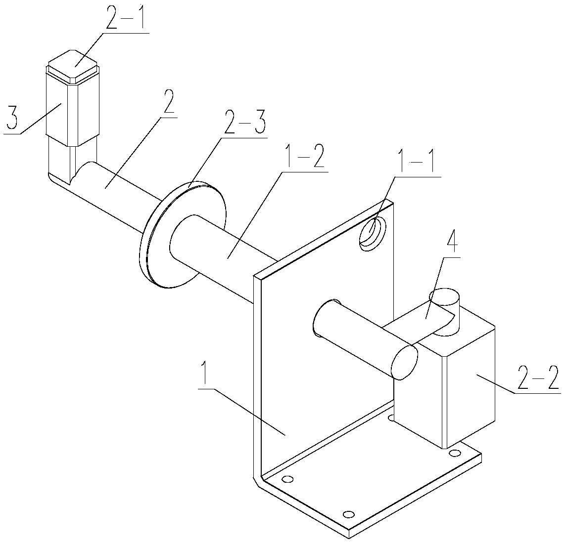
[0027] Such as Figure 1-5 As shown, a self-locking door stopper for opening the door includes a support 1 and a rotating shaft 2 passing through the support 1. The rotating shaft 2 is rotatably connected to the support 1. The outer end of the rotating shaft 2 is fixed with a door leaf 6 The stop rod 2-1 for position limiting, the inner end of the rotating shaft 2 is fixed with a counterweight 2-2, the stop rod 2-1 and the counterweight 2-2 are respectively located on both sides of the rotating shaft 2, the The weight of the counterweight 2-2 is greater than the weight of the stop bar 2-1, and a pushing ring 2-3 protrudes from the end of the rotating shaft 2 close to the stop bar 2-1, and the push ring 2-3 is located on the stop bar 2. Between -1 and counterweight 2-2;

[0028] A positioning pin 2-21 extends outward on the side of the counterweight 2-2 close to the support 1, and a pin hole 1-1 matching the positioning pin 2-21 is opened on the support 1, so that The positio...

Embodiment 2

[0037] Such as Figure 8-11 As shown, the difference between Embodiment 2 and Embodiment 1 is that: the support 1 is provided with a counterweight reset device, and the counterweight reset device includes a reset sleeve 7 and a return spring 8, and the support 1 is fixed There is a support plate 1-3, the reset sleeve 7 passes through the support plate 1-3, and is rotatably connected with the support plate 1-3, the reset sleeve 7 is axially positioned on the support plate 1-3, the reset sleeve 7 has an inner hole 7-1 with one end open, and the end of the rotating shaft 2 away from the blocking rod 2-1 extends outwards with an extension part 2-4, and the extension part 2-4 is slidably arranged in the inner hole 7-1. 1, and radially positioned in the inner hole 7-1, the extension part 2-4 of the rotating shaft 2 is inserted in the inner hole 7-1, the return spring 8 is located in the inner hole 7-1, One end of the return spring 8 abuts against the end face of the extension part ...


PUM


Abstract

The invention relates to the technical field of door stoppers, in particular to an opened door self-locking type door stopper which comprises a support and a rotating shaft penetrating through the support. The rotating shaft and the support are rotationally connected, a stop lever used for limiting a door page is fixed to the outer end of the rotating shaft, a balancing weight is fixed to the inner end of the rotating shaft, the stop lever and the balancing weight are located on the two sides of the rotating shaft correspondingly, the weight of the balancing weight is larger than that of the stop lever, a push ring is convexly arranged at the end, close to the stop lever, of the rotating shaft, the push ring is located between the stop lever and the balancing weight, a positioning pin extends outwards from the side, close to the support, of the balancing weight, and the support is provided with a pin hole matched with the positioning pin. Ingeniously, when opened to the position wherethe rotating shaft is located, the door page will drive the rotating shaft to produce axial displacement, therefore, the positioning pin on the balancing weight is disengaged from the pin hole in thesupport, the balancing weight will drive the rotating shaft to rotate under the self gravity effect, and finally the stop lever is automatically limited on the outer side of the door page. The openeddoor self-locking type door stopper is simple in structure, low in cost and high in reliability.

Description

technical field [0001] The invention relates to the technical field of door stoppers, in particular to a self-locking door stopper for door opening. Background technique [0002] The door stop is also commonly known as the door touch. It is also a device that absorbs and positions the door leaf after it is opened, so as to prevent the wind from blowing or touching the door leaf and closing it. All kinds of door stoppers use the principle of magnetic adsorption to hold and position the opened door leaf. The positioning effect of the door is not reliable. When the wind is strong, the suction head and the suction seat are easy to separate from each other, and the magnetic door stopper structure Complicated and expensive. Contents of the invention [0003] The technical problem to be solved by the present invention is: in order to solve the problem of unreliable positioning effect of the magnetic door stopper on the door leaf in the prior art, its complex structure and high c...

Claims


Application Information

Patent Timeline
Patent Type & Authority Applications(China)
IPC IPC(8): E05C17/46
CPCE05C17/46
Inventor 杨佳驹
Owner 常州联企知识产权代理有限公司
Why Eureka
Try Eureka