Microscopic vision system microscopic depth of field digital expansion method and system based on computer microscopic vision tomography technology

A technology of microscopic vision and tomography, which is applied in the direction of instruments, measuring devices, and optical devices, etc., can solve the problems of inability to observe, low precision, and technical difficulty of observation tasks, etc.

Active Publication Date: 2018-12-07
CHONGQING UNIV
View PDF3 Cites 3 Cited by
  • Summary
  • Abstract
  • Description
  • Claims
  • Application Information

AI Technical Summary

Problems solved by technology

[0003] The purpose of the present invention is to provide a solution for the observation of multiple parts across scales. Due to the contradictory problems of high resolution and large depth of field that are difficult to meet simultaneously in the microscopic v

Method used


Image

  • Microscopic vision system microscopic depth of field digital expansion method and system based on computer microscopic vision tomography technology
  • Microscopic vision system microscopic depth of field digital expansion method and system based on computer microscopic vision tomography technology
  • Microscopic vision system microscopic depth of field digital expansion method and system based on computer microscopic vision tomography technology

Examples


Embodiment 1

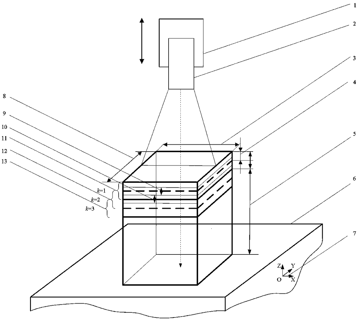
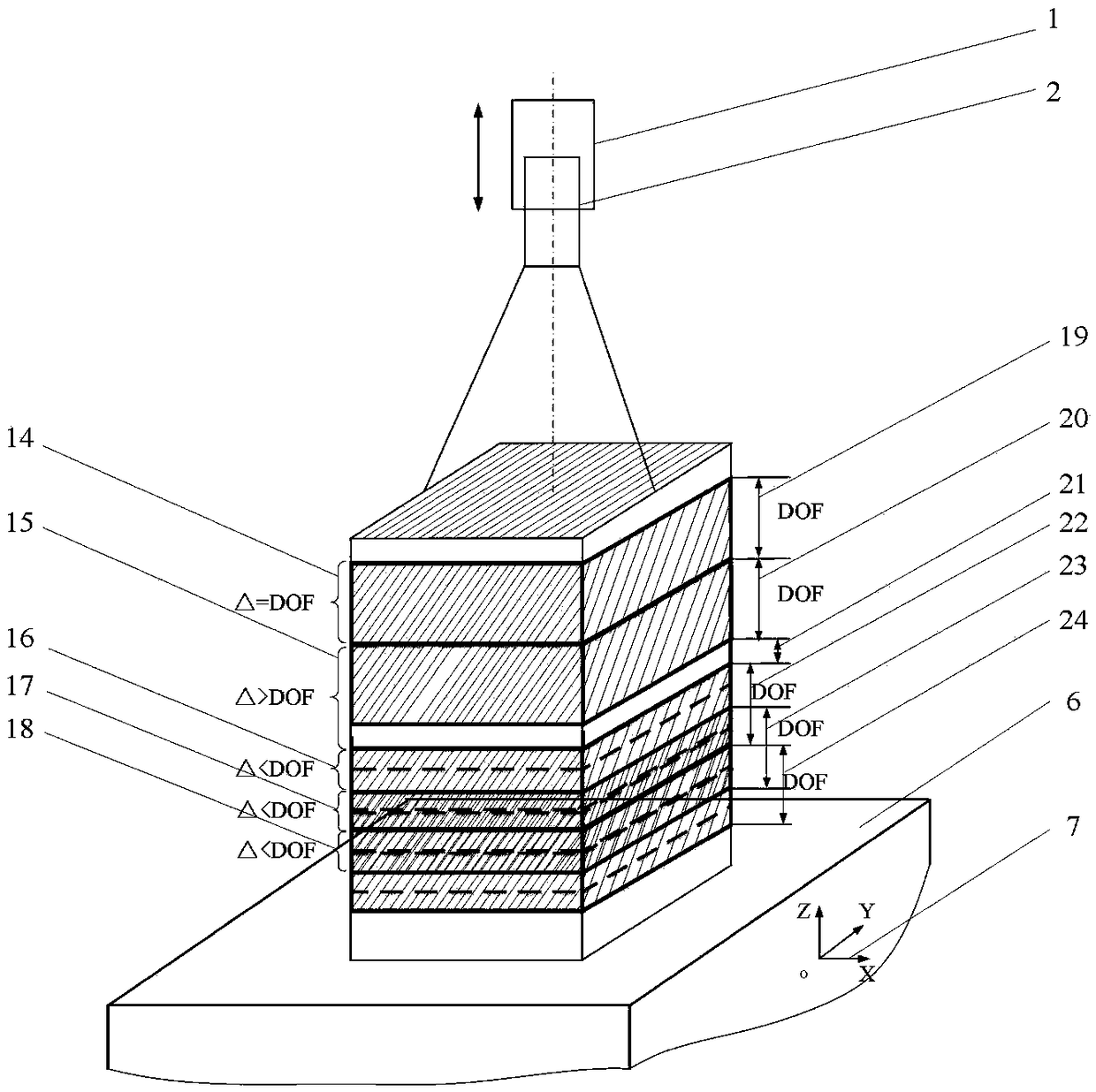
[0063] figure 1 Shown is a microscopic depth of field extension system based on computerized microvisual tomography technology for a monocular microscopic vision system, which has a precise positioning system I (1) to control the microscopic vision system I (2) along the defined coordinate system (7) The Z-axis direction of the microscopic field of view is tomographically scanned, and the step size constraint of the precise positioning system for tomographically is as follows: figure 2 shown. according to figure 2 The schematic diagram of the relationship between the step length of the precision positioning system and the depth of field of the microscopic vision system shown in the figure, as shown in the label (14), the depth of the three-dimensional fault space of the microvision system that performs tomographic scanning along the Z axis is DOF, At this time, the three-dimensional space is H×W×Δ; if ΔDOF, as As shown in the label (15), the space size of the three-dimens...

Embodiment 2

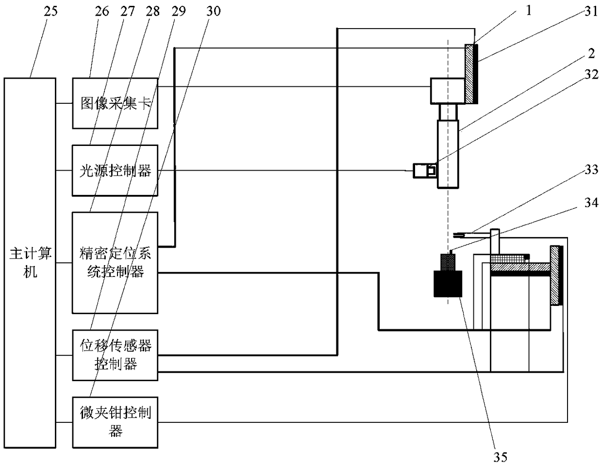
[0065] Figure 5 Shown is the depth of field extension system for the binocular orthogonal microscopic vision system, the hardware system structure of the depth of field extension of the binocular orthogonal microscopic vision system is as follows Image 6 with Figure 7 shown; where Figure 7 The precision positioning system II (40) is added to control the microscopic vision system II (39) to perform tomographic scanning on the microscopic field of view space in the horizontal direction, and the precision positioning system I (1) controls the microscopic vision system I (2) to perform tomographic scanning in the vertical direction. Carry out tomographic scanning of the microscopic field of view space in the vertical direction. In order to realize the high-precision displacement monitoring of the precision positioning system (1, 40), displacement sensors are installed respectively to realize displacement detection such as Image 6 As shown, the displacement sensors (31, 45)...

Embodiment 3

[0067] Figure 8Shown is the depth of field extension system for the trinocular orthogonal microscopic vision system, in which the precision positioning system III (47) and the control microvision system III (48) are added, and the precision positioning system (1, 40, 47) is respectively Controlling the microscopic vision system (2, 39, 48) to perform tomographic scanning along the Z axis, X axis, and Y axis defining the coordinate system (7), and acquiring tomographic image sequences respectively. The trinocular orthogonal microscopic vision system is based on the computer microscopic vision tomography technology. The hardware system structure of the microscopic scene depth expansion is as follows: Figure 9 , Figure 10 shown. exist Figure 9 In the middle, the precise positioning system I (1) controls the microscopic vision system I (2) to perform tomographic scanning on the microscopic field of view space along the vertical direction, and the precise positioning system ...


PUM


Abstract

The invention discloses a microscopic vision system microscopic depth of field digital expansion method and system based on a computer microscopic vision tomography technology. The microscopic visionsystem microscopic depth of field digital expansion method based on a computer microscopic vision tomography technology includes the steps: obtaining a tomographic image through the computer micro-visual tomography technique, and acquiring a three-dimensional tomographic field of view space corresponding to the tomographic image by combining the tomographic image with the step size of a precise positioning system; reconstructing the three-dimensional tomographic space digitized information by means of rasterization, digitization and other technologies; and finally, acquiring a digital microscopic field of view space with an expanded depth of field extension according to all the obtained digitized information of the tomographic space and tomographic space positional information, and then realizing expansion of the depth of field. The microscopic vision system microscopic depth of field digital expansion method based on a computer microscopic vision tomography technology overcomes the contradiction between high resolution and large depth of field, breaks through the limitation of being unable to obtain the ultra depth of field spatial information accurately because of the small depthof field of the microscopic vision system, and represents the microscopic vision field spatial information of the a micro assembly system with a large depth of field by means of the digitized information, thus visually and vividly representing the three-dimensional object information of the microscopic vision field space with the super depth of field.

Description

technical field [0001] The invention belongs to the field of intelligent manufacturing and scientific research, specifically serves the fields of micro-assembly and micro-operation, specifically relates to microscopic vision technology, and especially relates to the observation and operation of cross-scale objects in the microscopic viewing field space. Background technique [0002] The microscopic vision system is the key equipment for observing tiny parts, tiny objects, and cells. In order to be able to clearly observe the global shape information of objects of different sizes, it is necessary to adjust the depth of field of the microscopic vision system according to the size of different objects, which increases the difficulty of operation and reduces the observation accuracy of the microscopic vision system. Under high resolution and high magnification, the microscopic vision system can see small objects clearly, but the inverse relationship between resolution and depth ...

Claims


Application Information

Patent Timeline
IPC IPC(8): G01B11/24
CPCG01B11/24
Inventor 王代华王坎高贤永
Owner CHONGQING UNIV
Why Eureka
Try Eureka