
Waterproof USB socket and manufacturing method thereof

A technology of waterproof glue and connectors, which is applied to the assembly/disassembly of the base/housing, contact parts, electrical components, etc., and can solve the problems of being unable to achieve waterproofing

Active Publication Date: 2018-12-07
SHENZHEN EVERWIN PRECISION TECH
View PDF7 Cites 5 Cited by
  • Summary
  • Abstract
  • Description
  • Claims
  • Application Information

AI Technical Summary

Problems solved by technology

In order to prevent the socket from being damaged due to excessive insertion of the plug, the metal shell is generally stamped inward to form a number of baffles for resisting the metal shell of the plug. In this way, the metal shell of the socket forms a penetrating hole structure, which cannot be waterproof;

Method used


Image

  • Waterproof USB socket and manufacturing method thereof
  • Waterproof USB socket and manufacturing method thereof
  • Waterproof USB socket and manufacturing method thereof

Examples


Embodiment 1

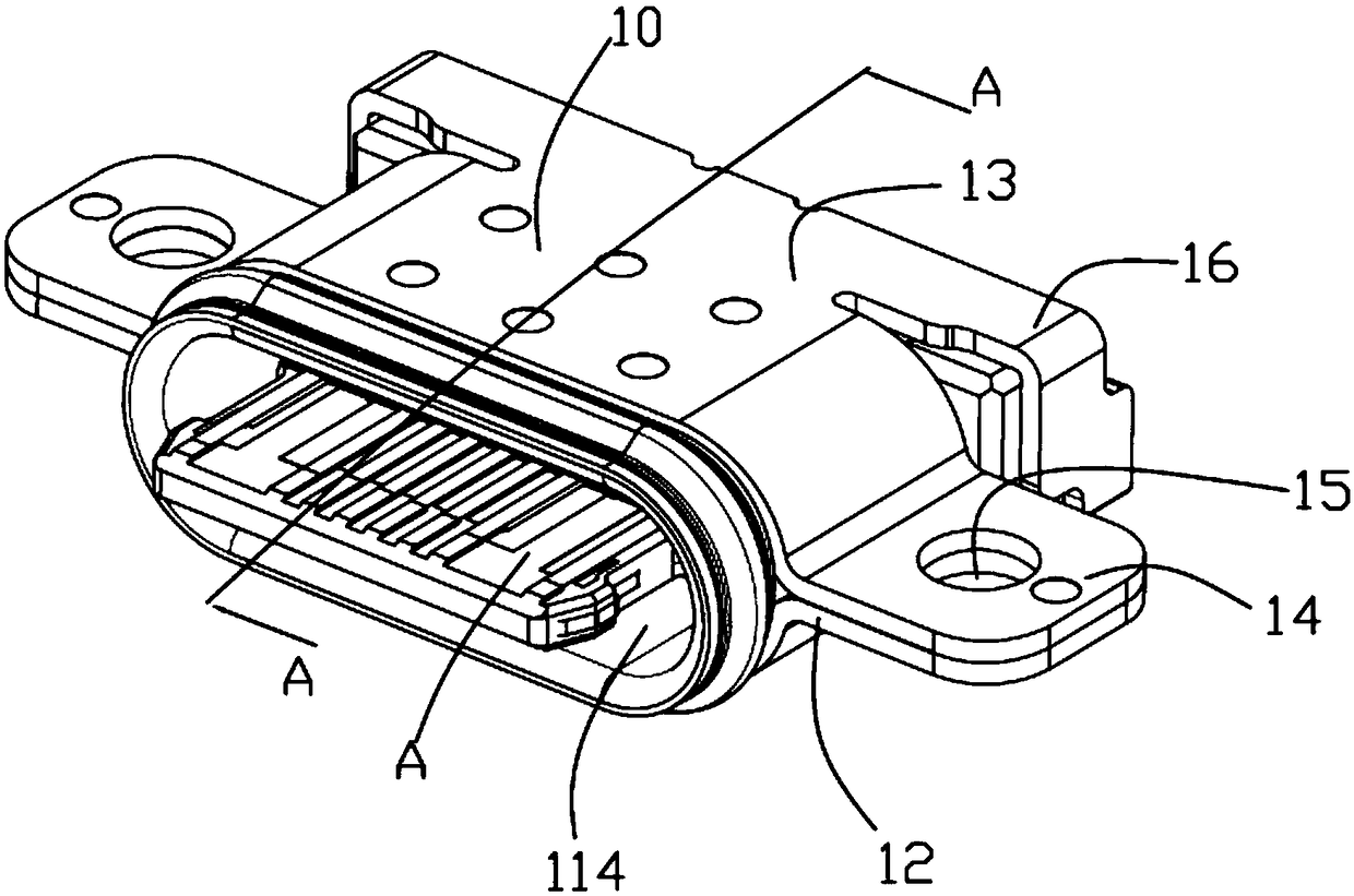
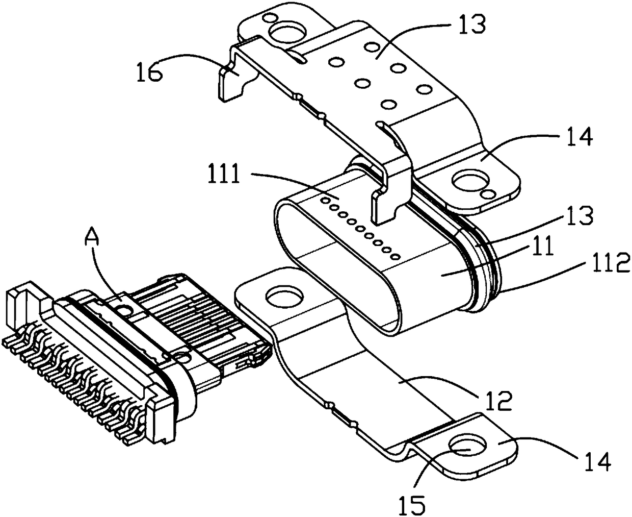
[0036] see Figure 1 to Figure 9 As shown, the waterproof USB socket of the present application includes a connector A, a metal shell 10 sleeved on the periphery of the connector A, waterproof glue filled in the tail of the connector A, and a metal shell sleeved on the metal shell. 10 the waterproof ring 113 of front end portion.

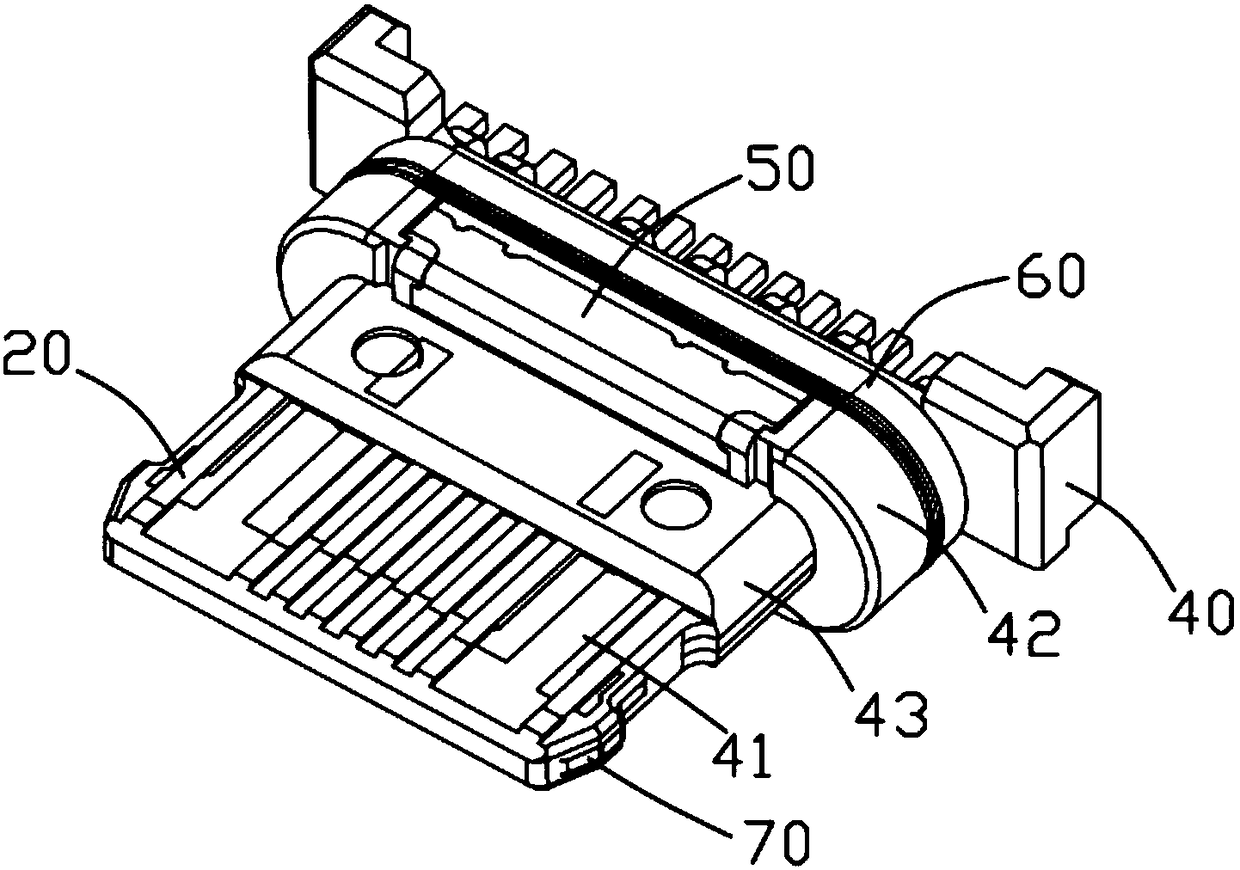
[0037] The connector A includes terminal groups 20 , 30 , a metal middle plate 70 , and an insulating body 40 integrally forming the terminal groups 20 , 30 and the metal middle plate 70 . The insulating body 40 includes a base portion 42 , a step portion 43 extending forward from the base portion 42 , and an abutting portion 41 extending forward from the step portion 43 . Parts of the terminal groups 20 , 30 are exposed on the upper and / or lower surfaces of the docking portion 41 to be in electrical contact with the docking connector.

[0038] The metal shell 10 includes a metal inner shell 11 sleeved on the periphery of the insulating body 40 , ...

Embodiment 2

[0055] see Figure 10 to Figure 13 As shown, the first embedded portion 54 of the blocking member 50 in this embodiment further includes a barb 543 bent and extended downward from the horizontal portion 542 . The second embedding portion 53 further includes a locking portion 531 bent vertically from the end of the second embedding portion 53 . The resisting portion 52 of the blocking member 50 also defines a positioning notch 56 .

[0056] In the first embodiment, the first and second plastic bodies 44 , 45 correspond to the accommodating groove 441 at the position of the base part 42 , and in the second embodiment, the accommodating platform 441 is used. The removal part 442 on the lateral outer side of the receiving platform 441 is provided with a card hole 443, and the rear end edge of the receiving platform 441 is provided with a card slot 444 for inserting the third embedded part 55, and the front end surface of the receiving platform 441 A positioning block 445 is prov...


PUM


Abstract

The invention provides a waterproof USB socket, which comprises a plug member, a metal housing sleeving the plug member, waterproof glue filling in the tail portion of the plug member, and a waterproof ring sleeving the metal housing. The plug member comprises a metal middle plate, first and second terminal groups arranged at the upper and lower sides of the metal middle plate respectively, and aninsulation body for enabling the metal middle plate and the first and second terminal groups to be fixedly integrated. The insulation body comprises a base portion, a step portion extending forward from the base portion, and a butting portion formed by extending forward from the step portion. The metal housing comprises a metal inner shell with a seamless peripheral wall. A stop member is inserted on the base portion of the insulation body. The stop member comprises a spot welding platform and an abutting-against portion formed on the front end surface of the base portion by bending forward from the spot welding platform and extending downward. The spot welding platform of the stop member is contacted with the metal inner shell and the two are integrated through spot welding. The invention also provides a manufacturing method of the waterproof USB socket.

Description

technical field [0001] The application relates to the field of connectors, in particular to a waterproof USB socket and a manufacturing method thereof. Background technique [0002] The USB socket generally includes a connector and a metal shell sheathed on the periphery of the connector, and the metal shell is provided with a receiving cavity for plug insertion. In order to prevent the socket from being damaged due to excessive insertion of the plug, the metal shell is generally stamped inward to form a number of baffles for resisting the metal shell of the plug. In this way, the metal shell of the socket forms a penetrating hole structure, which cannot be waterproof; Contents of the invention [0003] In view of this, it is necessary to provide a waterproof USB socket with good waterproof performance and a manufacturing method thereof. [0004] In order to solve the above technical problems, this application provides a waterproof USB socket, including a connector, a me...

Claims


Application Information

Patent Timeline
Patent Type & Authority Applications(China)
IPC IPC(8): H01R13/405H01R13/502H01R13/504H01R13/516H01R13/52H01R43/20H01R43/24
CPCH01R13/405H01R13/502H01R13/504H01R13/516H01R13/52H01R13/5202H01R13/521H01R13/5219H01R43/20H01R43/24
Inventor 顾远文
Owner SHENZHEN EVERWIN PRECISION TECH
Learn More