
Method and module for automatically adjusting projection image

A technology for automatic adjustment and adjustment of modules, applied in the field of projection, can solve problems such as poor user experience, failure to achieve intelligence, and unsatisfactory projection surface, so as to improve user experience and realize the effect of intelligence

Active Publication Date: 2018-12-07
CHENGDU XGIMI TECH CO LTD
View PDF8 Cites 10 Cited by
  • Summary
  • Abstract
  • Description
  • Claims
  • Application Information

AI Technical Summary

Problems solved by technology

[0003] In the process of using a projector, sometimes the projection surface is not ideal, and the projection screen cannot be displayed in full size on the projection surface. It is necessary to reduce the size of the projection screen to fit the projection surface. However, the current projector cannot effectively analyze the appropriate projection area. It is necessary to manually adjust the projection screen to find a suitable projection area for projection, which cannot be intelligent and the user experience is not good

Method used


Image

  • Method and module for automatically adjusting projection image
  • Method and module for automatically adjusting projection image

Examples


Embodiment

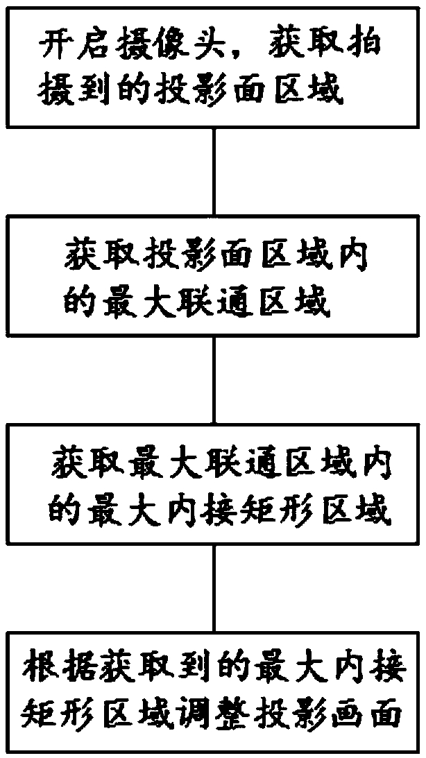
[0040] Such as figure 1 As shown, this embodiment provides a method for automatically adjusting the projection screen, including:

[0041] Step S1: Turn on the camera to obtain the projected area of ​​the projection surface;

[0042] Step S2: Obtain the largest connected area within the projection area;

[0043] Step S3: Obtain the largest inscribed rectangular area within the largest connected area;

[0044] Step S4: Adjust the projection screen according to the acquired largest inscribed rectangular area.

[0045] Specifically, the step of obtaining the largest connected area in the projection area, that is, step S2, specifically includes:

[0046] Step S211: according to the gray information similarity algorithm, mark the projection surface image areas with similar gray values ​​as the same area;

[0047] Step S212: Obtain all Unicom areas in the same area;

[0048] Step S213: Acquire the number of pixels in each connected area, and determine the area with the largest ...

Embodiment 2

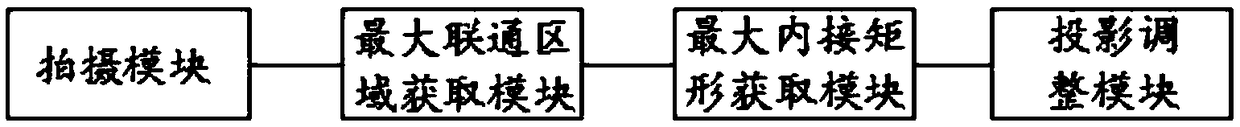
[0065] Such as figure 2 As shown, this embodiment provides a module for automatically adjusting the projection screen, and the automatic projection adjustment can be performed by using the method for automatically adjusting the projection screen provided in Embodiment 1, including:

[0066] Shooting module: used to shoot the projection surface area and transmit the captured projection surface area information to the maximum Unicom area acquisition module;

[0067] The maximum Unicom area acquisition module: used to calculate the maximum Unicom area according to the projection screen area information transmitted by the shooting module and transmit the maximum Unicom area information to the largest inscribed rectangle acquisition module;

[0068] Maximum inscribed rectangle acquisition module: used to calculate the maximum inscribed rectangle according to the maximum Unicom area information transmitted by the maximum Unicom area acquisition module and transmit the maximum inscr...


PUM


Abstract

The invention discloses a method for automatically adjusting a projection image. The method comprises the following steps: opening a camera to obtain a captured projection surface area; obtaining a maximum communication area in the projection surface area; obtaining a maximum inscribed rectangular area in the maximum communication area; and adjusting the projection image according to the obtainedmaximum inscribed rectangular area. According to the method disclosed by the invention, the maximum communication area is obtained first, then the maximum inscribed rectangular area is obtained in themaximum communication area to serve as the most proper projection area, and finally the projection image is automatically adjusted according to the maximum inscribed rectangular area, intelligence isachieved, and the user experience is improved.

Description

technical field [0001] The invention relates to the field of projection, in particular to a method and module for automatically adjusting projection images. Background technique [0002] A projector, also known as a projector, is a device that can project images or videos onto a screen or a plane. It can be connected to a computer, VCD, DVD, BD, game console, DV, etc. through different interfaces to play the corresponding video. Signal, projectors are currently widely used in homes, offices, schools, and entertainment venues. According to different working methods, there are different types such as CRT, LCD, and DLP. [0003] In the process of using a projector, sometimes the projection surface is not ideal, and the projection screen cannot be displayed in full size on the projection surface. It is necessary to reduce the size of the projection screen to fit the projection surface. However, the current projector cannot effectively analyze the appropriate projection area. It...

Claims


Application Information

Patent Timeline
IPC IPC(8): H04N9/31
CPCH04N9/3185
Inventor 钟波肖适刘志明宁仲
Owner CHENGDU XGIMI TECH CO LTD
Features
  • Generate Ideas
  • Intellectual Property
  • Life Sciences
  • Materials
  • Tech Scout
  • Unparalleled Data Quality
  • Higher Quality Content
  • 60% Fewer Hallucinations
Learn More