Shank correction device

A calf and mounting plate technology, applied in passive exercise equipment, physical therapy, etc., can solve problems such as difficulty in persisting and strenuous calf stretching methods, and achieve the effect of preventing upper body from shaking and facilitating adjustment

Inactive Publication Date: 2018-12-11
骆思明
View PDF17 Cites 3 Cited by
  • Summary
  • Abstract
  • Description
  • Claims
  • Application Information

AI Technical Summary

Problems solved by technology

[0003] In order to overcome the shortcomings of the current calf stretching method that is very strenuous, difficult to persist, and limited by the looseness of people's clothing, the te

Method used


Image

  • Shank correction device
  • Shank correction device
  • Shank correction device

Examples


Embodiment 1

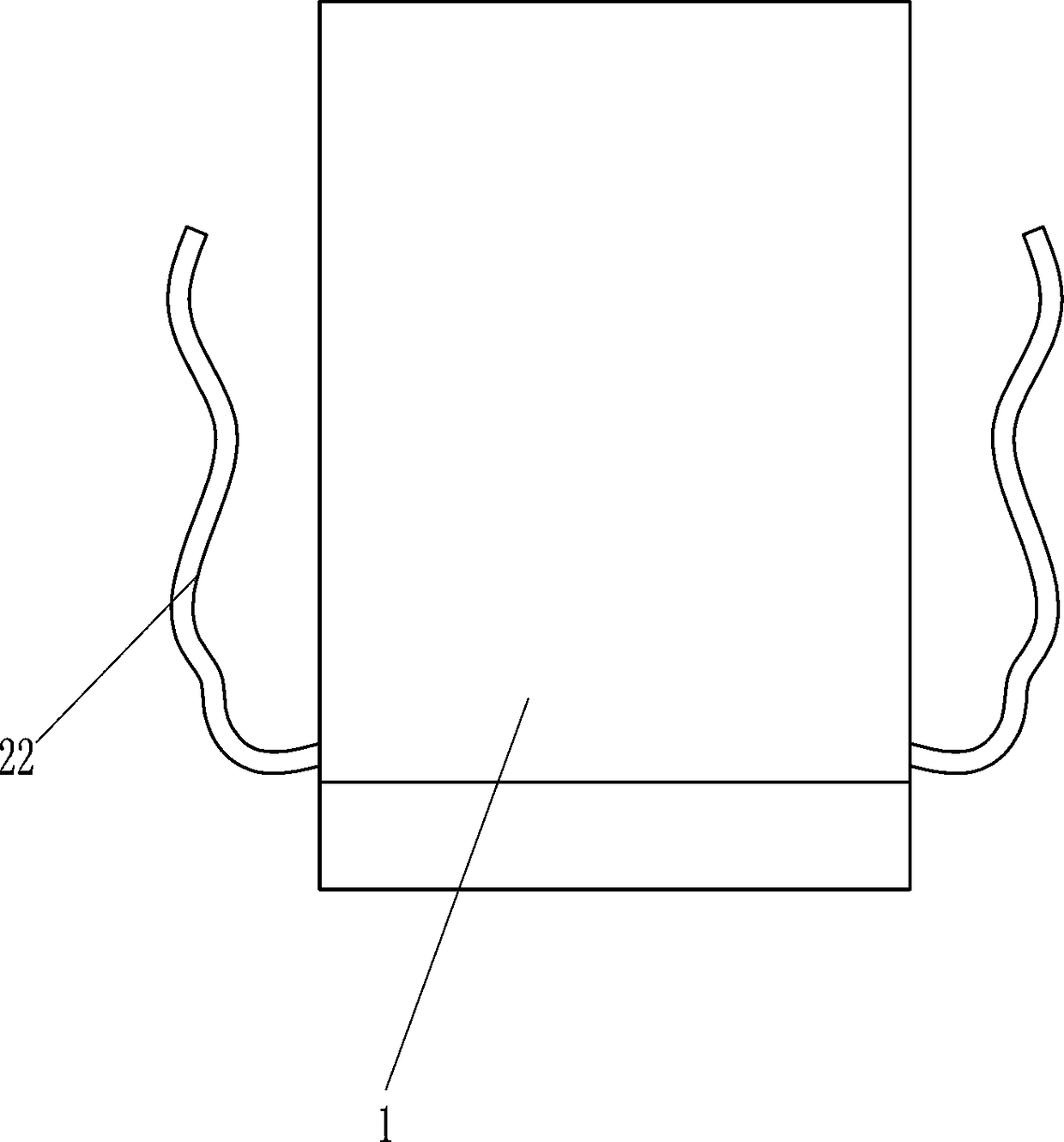
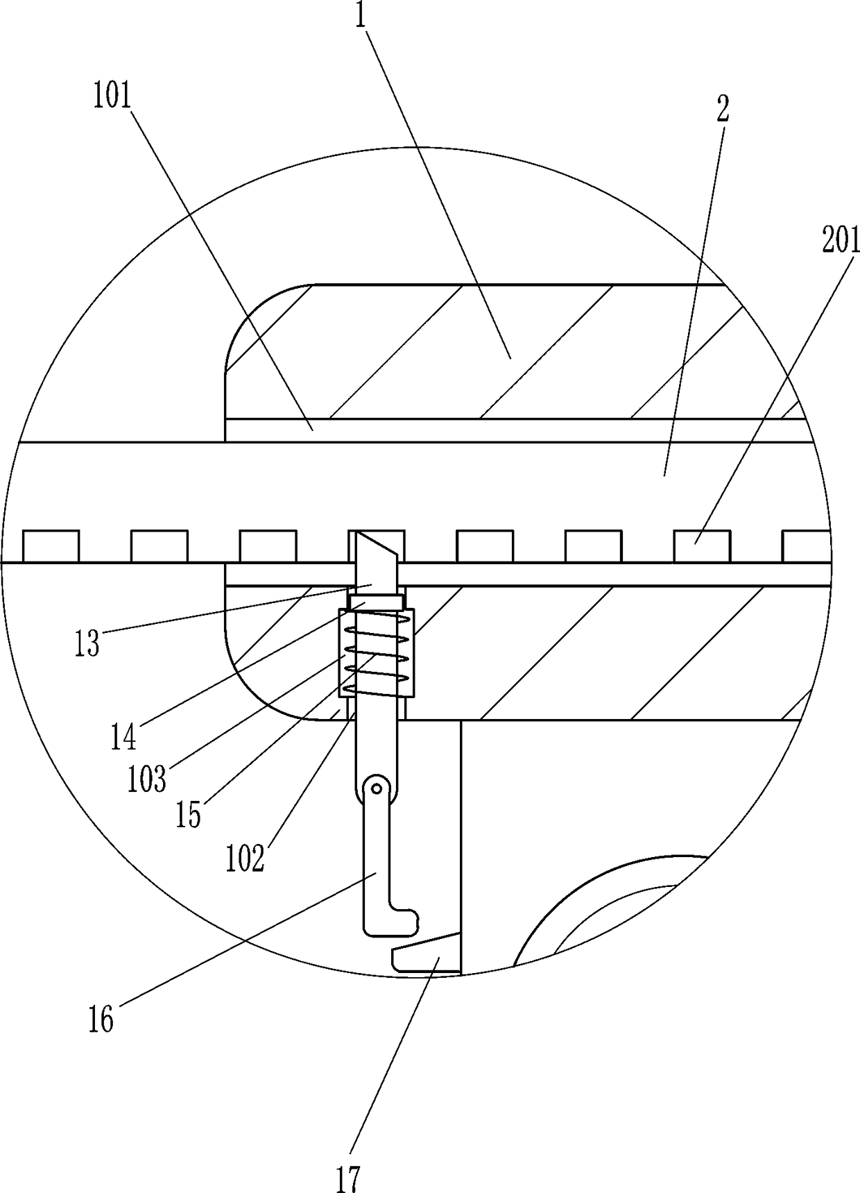
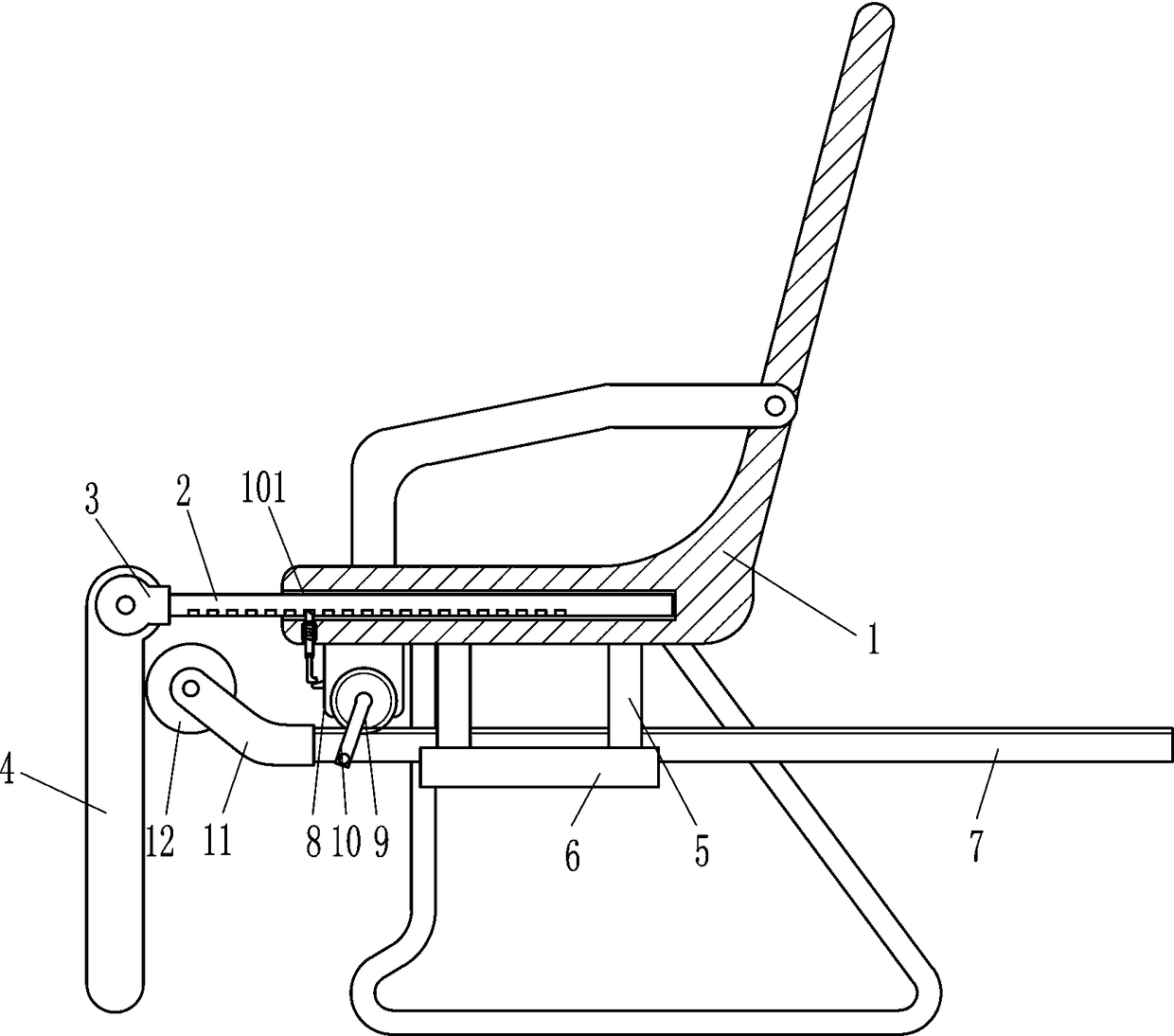
[0016] A calf correction device such as Figure 1-4 As shown, it includes chair 1, slide bar 2, hinge seat 3, correction board 4, vertical bracket 5, guide rail 6, rack 7, mounting plate 8, gear 9, crank 10, arc bracket 11, roller 12, insert Rod 13, stop block 14, spring 15, long U-shaped rod 18, rotating sleeve 19, adhesive tape 20, short U-shaped rod 21 and binding rope 22, the lower part of chair 1 has a chute 101, and the movable type in the chute 101 A slide bar 2 is provided, and a plurality of grooves 201 are evenly spaced at the bottom of the slide bar 2. The front and rear parts on the left side of the slide bar 2 are connected with a hinged seat 3, and the hinged seat 3 is rotatably connected with a correcting plate 4. The correcting plate 4 The front side is connected with a long U-shaped bar 18, and the long U-shaped bar 18 is covered with a plurality of rotating sleeves 19, and the rotating sleeve 19 is connected with an adhesive tape 20, and the rear side of the ...

Embodiment 2

[0018] A calf correction device such as Figure 1-4 As shown, it includes chair 1, slide bar 2, hinge seat 3, correction board 4, vertical bracket 5, guide rail 6, rack 7, mounting plate 8, gear 9, crank 10, arc bracket 11, roller 12, insert Rod 13, stop block 14, spring 15, long U-shaped rod 18, rotating sleeve 19, adhesive tape 20, short U-shaped rod 21 and binding rope 22, the lower part of chair 1 has a chute 101, and the movable type in the chute 101 A slide bar 2 is provided, and a plurality of grooves 201 are evenly spaced at the bottom of the slide bar 2. The front and rear parts on the left side of the slide bar 2 are connected with a hinged seat 3, and the hinged seat 3 is rotatably connected with a correcting plate 4. The correcting plate 4 The front side is connected with a long U-shaped bar 18, and the long U-shaped bar 18 is covered with a plurality of rotating sleeves 19, and the rotating sleeve 19 is connected with an adhesive tape 20, and the rear side of the ...


PUM


Abstract

The invention relates to a correction device, in particular to a shank correction device. By the aid of the shank correction device, labor can be saved, people are willing to keep going, and limitation of dressing fitness is omitted. The shank correction device comprises a chair, a sliding rod, hinge seats, a correction plate, a vertical support, a guide rail, a rack, a mounting plate, a gear, a crank, an arc-shaped support, rollers, inserting rods, limit blocks and the like. A sliding groove is formed in the lower portion of the chair, the sliding rod is movably arranged in the sliding groove, a plurality of grooves are uniformly formed in the bottom of the sliding rod at intervals, the front and the back of the left side of the sliding rod are connected with the hinge seats, and the hinge seats are rotatably connected with the correction plate. A user pulls the inserting rods to move downwards and moves the sliding rod, the distance between the correction plate and the chair can be adjusted according to different requirements, and the inserting rods move upwards and are inserted into the corresponding grooves, so that the sliding rod can be fixed and prevented from randomly moving.

Description

technical field [0001] The invention relates to a correcting device, in particular to a calf correcting device. Background technique [0002] When a person does not exercise for a long time and lacks calf exercises, the calf muscles tend to turn inward or outward, and even atrophy occurs and cannot be stretched. Similarly, under the condition of long-term training, the calf muscles tend to become dead muscles and lose the explosiveness of normal muscles. Therefore, after exercising, the calf should also be properly massaged and stretched to allow the muscles to fully contract to improve muscle tension. form. At present, the general stretching method is to lift the feet up, bend the body, make the head as close to the feet as possible to press the legs, or stretch one leg forward and keep it straight, and then bend it back to stretch, etc. These calf stretching methods are very laborious. The stretch is too large, it is difficult for people to stick to it, and it is largely...

Claims


Application Information

Patent Timeline
IPC IPC(8): A61H1/02
CPCA61H1/0218A61H1/0237A61H2201/0149A61H2201/1253A61H2201/1642A61H2205/106
Inventor 骆思明
Owner 骆思明
Why Eureka
Try Eureka