[0030] The technical solutions in the embodiments of the present invention will be clearly and completely described below in conjunction with the accompanying drawings in the embodiments of the present invention. Obviously, the described embodiments are only a part of the embodiments of the present invention, rather than all the embodiments. Based on the embodiments of the present invention, all other embodiments obtained by those of ordinary skill in the art without creative work shall fall within the protection scope of the present invention.
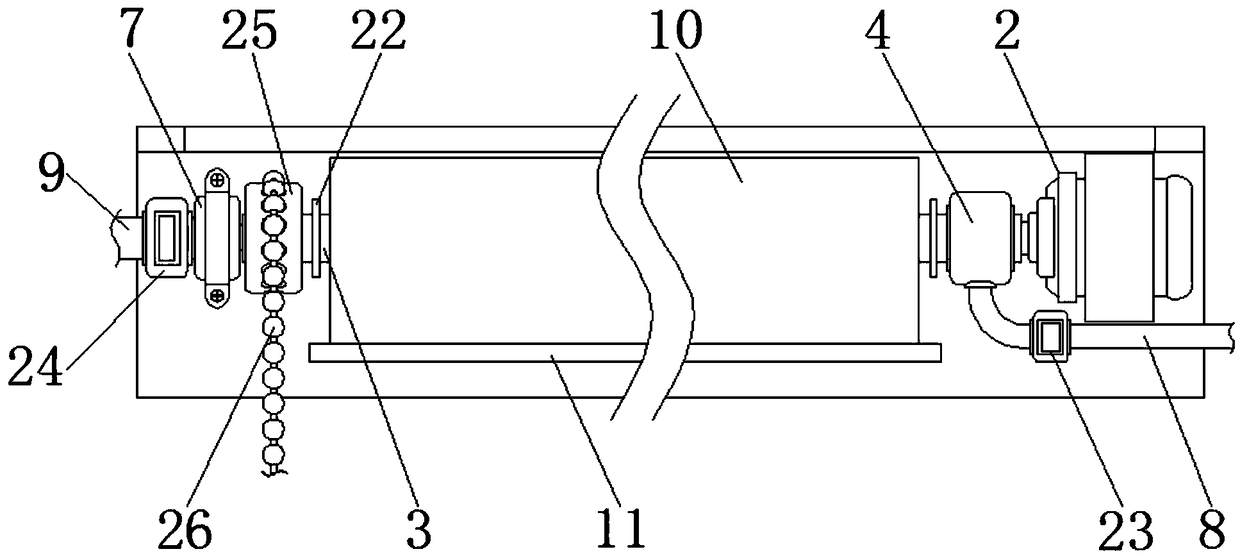
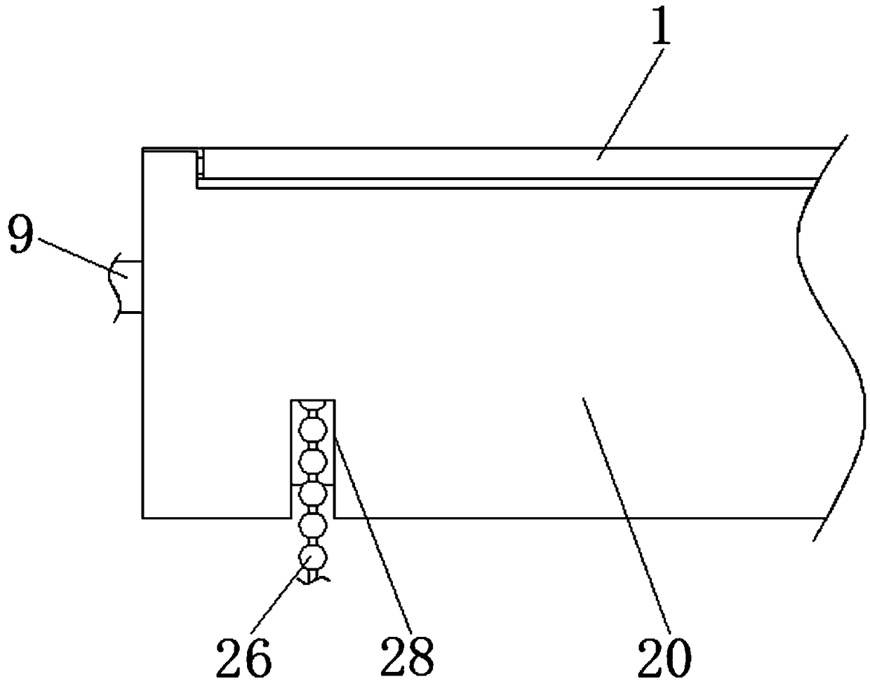
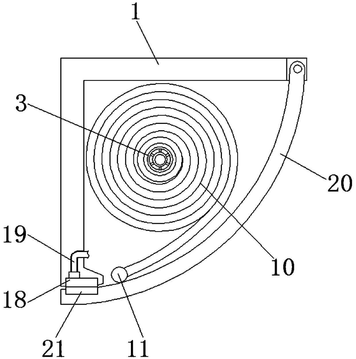
[0031] See Figure 1-6 The embodiment of the present invention provides a technical solution: a fire prevention device for building facades includes a right-angle fixed frame 1, the bottom of the right-angle fixed frame 1 is fixedly connected to an electromagnetic strip 18, and the top of the electromagnetic strip 18 is fixedly connected to a wire 19 , The end of the wire 19 away from the electromagnetic strip 18 penetrates the right-angle fixed frame 1 and extends to the inside of the right-angle fixed frame 1. The front of the right-angle fixed frame 1 is rotatably connected with an arc-shaped hidden plate 20, and the surface of the arc-shaped hidden plate 20 is provided with beads The slot 28 is adapted to the chain 26, the slot 28 is provided to facilitate the placement of the bead chain 26, the back of the arc-shaped hidden plate 20 and the position corresponding to the electromagnetic strip 18 is fixedly connected with the permanent magnet strip 21, and the arc-shaped hidden plate is set 20 can hide the internal device, and then can maintain the aesthetics. Normally, the electromagnetic strip 18 can attract each other with the permanent magnet strip 21 when the electromagnetic strip 18 is not energized, and then attract the arc-shaped hidden plate 20. After being energized, it can interact with the permanent magnet. The strip 21 generates a reverse magnetic force to push out the arc-shaped hidden plate 20 to facilitate the fall of the flameproof film 10. The right side of the inner surface of the right-angle fixed frame 1 is fixedly connected to the motor 2 through a fixed sleeve, and the left end of the output shaft of the motor 2 is fixedly connected There is a hollow shaft 3, the surface of the hollow shaft 3 and on both sides of the flameproof membrane 10 are fixedly connected to the limit ring 22, the surface of the air inlet pipe 8 and the water inlet pipe 9 and located inside the right-angle fixed frame 1 are respectively fixedly connected to the first The solenoid valve 23 and the second solenoid valve 24, the first solenoid valve 23 and the second solenoid valve 24 can be used to control the conduction between the air inlet pipe 8 and the water inlet pipe 9 in time to avoid accidental filling of the flameproof membrane 10 with water during daily use Or gas, causing the anti-combustion film 10 to collapse, ensuring the safe use of the device. The surface of the hollow shaft 3 and the side of the limit ring 22 is fixedly connected with a rotating block 25, and the surface of the rotating block 25 is sheathed with a bead chain 26 , And the surface of the rotating block 25 is provided with a groove adapted to the bead chain 26. The bead chain 26 is stuck in the groove to drive the rotating block 25 to rotate. Through the cooperation of the bead chain 26 and the surface groove of the rotating block 25, Manually control the rotation of the hollow shaft 3 to roll up the flameproof film 10, which avoids the problem of insufficient power of the motor 2 and difficulty in rolling up the flameproof film 10, and the operation is convenient and easy. The right end of the hollow shaft 3 is connected to the first pipe connector 4 , The first pipe connecting piece 4 and the hollow shaft 3 can be rotated while maintaining communication, and the surface of the first pipe connecting piece 4 is fixedly connected with the inner surface of the right-angle fixed frame 1, and the inner surface of the hollow shaft 3 is connected by a short The column 5 is fixedly connected with an inner tube 6, the left end of the inner tube 6 penetrates the hollow shaft 3 and extends to the left end of the hollow shaft 3, and the left end of the inner tube 6 is connected with a second pipe connector 7 which is connected to the inner tube 6 The cylinders 6 can be rotated while maintaining communication. The surface of the second pipe connecting piece 7 is fixedly connected with the inner surface of the right-angle fixed frame 1. The surface of the first pipe connecting piece 4 is connected with an air inlet pipe 8, which is connected to the outside The air pump is connected. The left side of the second pipe connector 7 is connected with a water inlet pipe 9, which is connected to an external water pump. The surfaces of the hollow shaft 3 and the inner cylinder 6 are both penetrated with a flameproof membrane 10, which is made of fire-resistant material , It can be fireproof, and the flameproof film 10 is fixed on the side away from the inner cylinder 6 A load bar 11 is fixedly connected. In the event of a fire, the hollow shaft 3 is driven to rotate by the motor 2 to quickly lay down the flame retardant film 10 wound on the surface. The gravity of the load bar 11 makes the flame retardant film 10 hang down naturally, thereby allowing It shields the wall to facilitate water spraying and air jets. It adopts electric mode and is quick and convenient to operate. The interior of the flameproof film 10 is divided into a gas cavity 13 and a water cavity 14 by a diaphragm 12, and the surface of the flameproof film 10 is located One side of the gas cavity 13 is provided with a jet hole 29, and the surface of the anti-combustion film 10 is provided with a water jet hole 27 on one side of the water cavity 14. The hollow shaft 3, the inner cylinder 6 and the air inlet pipe 8, and the water inlet pipe 9 Connection, air and water can be introduced into the flameproof film 10 respectively, and the air jet can be jetted in the direction of the fire source through the air jet hole 29 to blow the fire away from the wall, while the water jet hole 27 can spray water to the wall to hit the wall. Wet, the two methods work at the same time, which can prevent the fire from igniting the wall during the fire, which can reduce the spread of the fire, and the effect is better. One side of the flameproof film 10 and located inside the inner cylinder 6 is fixedly connected with a water inlet 15 , The surface of the water inlet bar 15 is connected to the water cavity 14. The gas cavity 13 is movably connected with a gas outlet block 16 which can open the gas cavity 13 to prevent the flameproof film 10 from being flattened under the pressure, and the gas cannot enter the gas In the cavity 13, one side of the air outlet block 16 is connected with an air inlet 17, and one side of the air inlet 17 penetrates the flameproof film 10 and extends between the inner cylinder 6 and the hollow shaft 3.
[0032] When in use, fix the right-angle fixed frame 1 at the corner of the top of the wall. When a fire occurs, start the device manually or by an external sensor. The electromagnetic strip 18 is first energized, and the electromagnetic strip 18 is generated with the permanent magnet strip 21. The magnetic force in the opposite direction pushes the arc-shaped concealed plate 20 away, and then the motor 2 rotates to make the hollow shaft 3 rotate, and the flameproof film 10 wound on the surface is put down, and the gravity of the load bar 11 makes the flameproof film 10 fall naturally. Make it cover the wall, then open the first solenoid valve 23, the second solenoid valve 24, use the external water pump to inject water into the inner cylinder 6 through the water inlet pipe 9 and the second pipe connector 7, and then the water passes through the water inlet The strip 15 enters the water chamber 14, and finally sprays from the spray hole 27 to the wall. At the same time, the external air pump fills the air between the hollow shaft 3 and the inner cylinder 6 through the air inlet pipe 8 and the first pipe connection 4, and the air enters The gas nozzle 17 enters, fills into the gas cavity 13 through the gas outlet block 16, and then sprays out from the jet hole 29 to blow the flame outward. After use, close the device, manually pull the bead chain 26, and use the rotating block 25 to make the hollow shaft 3 Rotate to roll up the flameproof film 10, and finally push the arc-shaped concealed plate 20 with a rod, so that the electromagnetic strip 18 and the permanent magnet strip 21 attract each other, and the arc-shaped concealed plate 20 is fixed.
[0033] It should be noted that in this article, relational terms such as first and second are only used to distinguish one entity or operation from another entity or operation, and do not necessarily require or imply one of these entities or operations. There is any such actual relationship or order between. Moreover, the terms "include", "include" or any other variants thereof are intended to cover non-exclusive inclusion, so that a process, method, article or device including a series of elements not only includes those elements, but also includes those that are not explicitly listed Other elements of, or also include elements inherent to this process, method, article or equipment.
[0034] Although the embodiments of the present invention have been shown and described, those of ordinary skill in the art can understand that various changes, modifications, and substitutions can be made to these embodiments without departing from the principle and spirit of the present invention. And variations, the scope of the present invention is defined by the appended claims and their equivalents.