Improved sealing ring type mold

A sealing ring and an improved technology, which is applied in household appliances, other household appliances, household components, etc., can solve the problems of difficult precise control of unit consumption, unfavorable mold repair and maintenance, easy damage to mating surfaces, etc.

Pending Publication Date: 2018-12-11
安徽宁国中鼎模具制造有限公司
View PDF0 Cites 1 Cited by
  • Summary
  • Abstract
  • Description
  • Claims
  • Application Information

AI Technical Summary

Problems solved by technology

[0002] like figure 1 As shown, there are 3 types of existing seal ring molds, one of which adopts the interference inlay design, and the other 2 adopts the edge tearing design, resulting in 2 flashes, which need to be manually torn off later, while the current Molded structure, the unit consumption is difficult to control accurately, in order not to lack materials, the actual unit consumption is usually much higher than the theoretical unit consumption, which results in a very thick flash of the product, especially the flash thickness of the inner circle is greater than 0.15mm , resulting in increased difficulty in tearing flash in the rear channel, reduced efficiency, and decreased product qualification rate; the surface seals used between the upper mold and the middle mold, and the upper mold and the mold core have a large pressure-bearing area and a small pressure per unit area, resulting in rubber The flash is difficult to be thinned; there is no excess material groove designed, and the excess rubber has nowhere to go, and it accumulates at the parting surface, resulting in too thick rubber flash; the lower mold is an inlaid structure, and the two inserts are interference fit. The insert is difficult to disassemble, and the mating surface is easily damaged during the disassembly process, which is not conducive to the later repair and maintenance of the mold; when the product is demoulded, the rubber product is wrapped in the lower mold, and the conventional demoulding device cannot be used, and manual demoulding is required. When removing the mold manually, it takes a lot of force to remove it one by one. Usually this type of mold has 25-36 cavities per mold, so the labor intensity of the workers is high, the time is long, and the production efficiency is low.

Method used


Image

  • Improved sealing ring type mold
  • Improved sealing ring type mold

Examples


Embodiment Construction

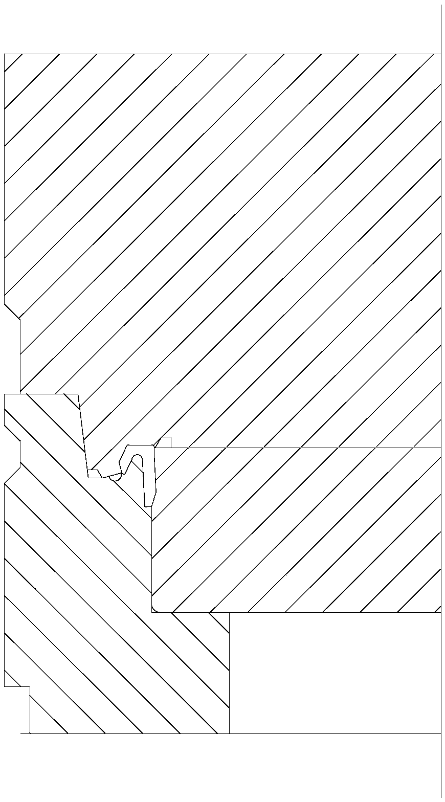
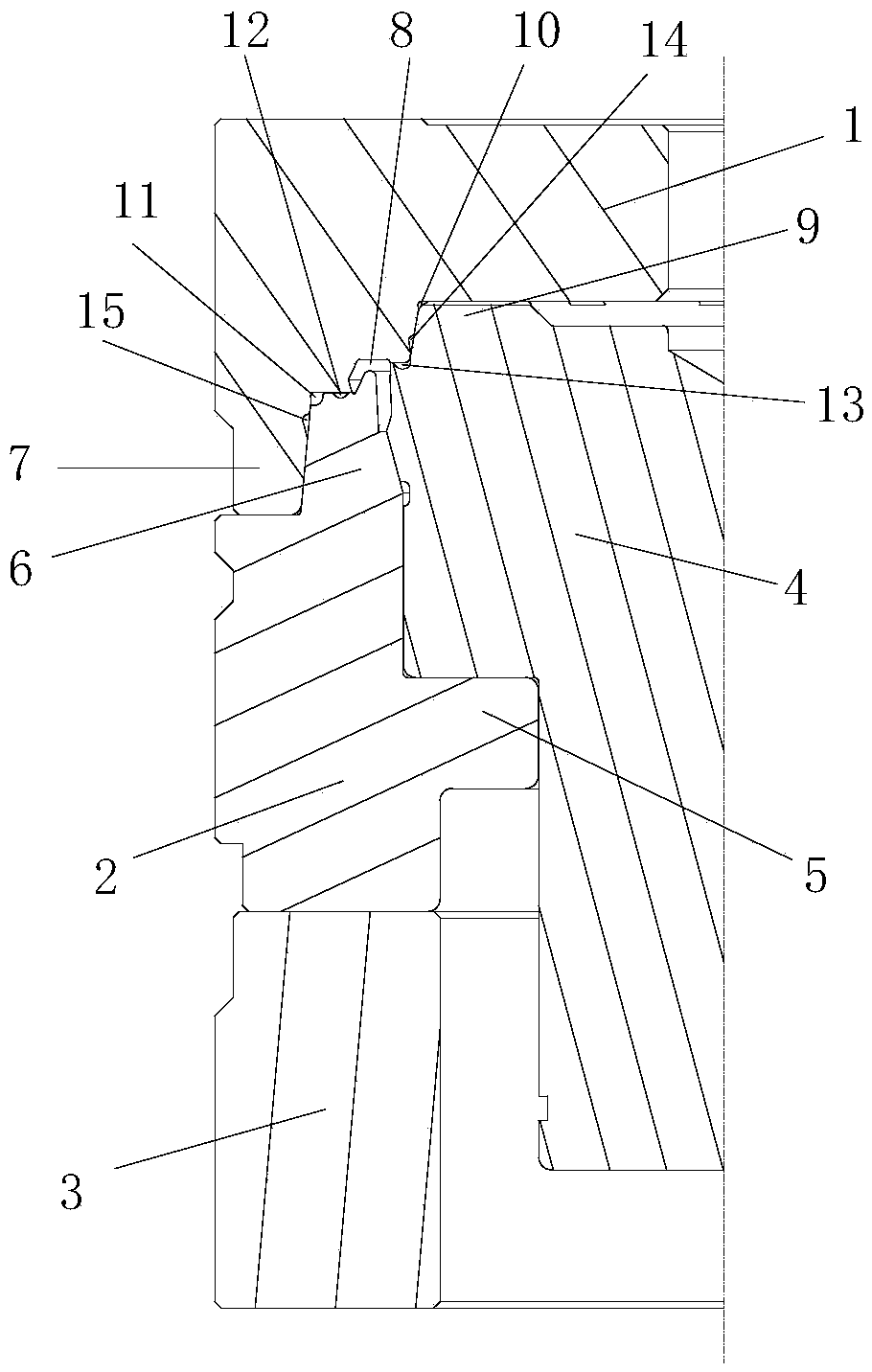
[0014] refer to figure 2 , the present invention proposes an improved sealing ring mold, which includes an upper mold 1 , a middle mold 2 , a lower mold 3 and a mold core 4 in an annular structure. The upper mold 1 and the lower mold 3 are arranged up and down, the mold core 4 is set between the upper mold 1 and the lower mold 3 and the middle mold 2 is set outside the mold core 4, and the inner side of the middle mold 2 is provided with a ring platform 5 for supporting the mold core 4 The top surface of the middle mold 2 is provided with a first annular protruding platform 6, and the outer edge of the bottom surface of the upper mold 1 is provided with a second annular protruding platform 7. In the mold closing state, the top surface of the lower mold 3 is in contact with the bottom surface of the middle mold 2, the top surface of the first annular raised platform 6 is in contact with the bottom surface of the upper mold 1, and the bottom surface of the second annular raised...


PUM


Abstract

The invention provides an improved sealing ring type mold, which comprises an upper mold of an annular structure, a middle mold, a lower mold and a mold core, wherein the upper mold and the lower moldare in vertical arrangement; the mold core is arranged between the upper mold and the lower mold; the middle mold is arranged outside the mold core; the inner side of the middle mold is provided witha ring table used for supporting the mold core; the top surface of the middle mold is provided with a first annular lug boss; the outer edge of the bottom surface of the upper mold is provided with asecond annular lug boss; in the mold matching state, the top surface of the lower mold is abutted against the bottom surface of the middle mold; the top surface of the first annular lug boss is abutted against the bottom surface of the upper mold; the bottom surface of the second annular lug boss is abutted against the top surface of the middle mold; the inner side surface of the second annular lug boss is abutted against the outer side surface of the first annular lug boss; the top surface of the mold core is abutted against the bottom surface of the upper mold; the outer side surface of themold core is abutted against the inner side surface of the middle core; a die cavity is formed among the upper mold, the first annular lug boss and the mold core. The flange-free design is used between the middle mold and the mold core; the flange in the shaping position between the upper mold and the middle mold and between the upper mold and the mold core is controlled to be 0 to 0.02mm; the flange is automatically separated from a product during demolding.

Description

technical field [0001] The invention relates to the technical field of sealing ring molds, in particular to an improved sealing ring mold. Background technique [0002] Such as figure 1 As shown, there are 3 types of existing seal ring molds, one of which adopts the interference inlay design, and the other 2 adopts the edge tearing design, resulting in 2 flashes, which need to be manually torn off later, while the current Molded structure, the unit consumption is difficult to control accurately, in order not to lack materials, the actual unit consumption is usually much higher than the theoretical unit consumption, which results in a very thick flash of the product, especially the flash thickness of the inner circle is greater than 0.15mm , resulting in increased difficulty in tearing flash in the rear channel, reduced efficiency, and decreased product qualification rate; the surface seals used between the upper mold and the middle mold, and the upper mold and the mold core...

Claims


Application Information

Patent Timeline
Patent Type & Authority Applications(China)
IPC IPC(8): B29C43/36B29L31/26
CPCB29C43/36B29L2031/265
Inventor 郭继刚陈增宝韩双能喻家程马进孔文武胡昊韩传龙
Owner 安徽宁国中鼎模具制造有限公司
Why Eureka
Try Eureka