
Eureka
For R&D, Eureka makes reading and utilizing patents & technical documents easy.
Eureka AIR
Designed for self-driven R&D workflows. Generate viable solutions, solve complex R&D challenges, empower your innovation with AI.

Eureka Materials
Designed for material experts only. Revolutionize your material R&D, from search, analyze, to developing new materials.

TechResearch
Generate reliable direction feasibility study reports for your R&D in just a few steps.

TechSeek
Discover and master advanced knowledge NOW. Basics, ideas, possibilities, all at once.

TechMind
As an expert in R&D Theories, TechMind can generates customized viable solutions instantly.

TechRisk
Analyze your overall solution with one click, know your potential R&D risks in advance.

TechMonitor
Get weekly tech updates, stay abreast of the latest tech innovations and key insights.
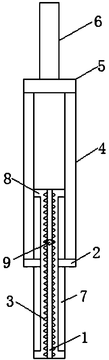
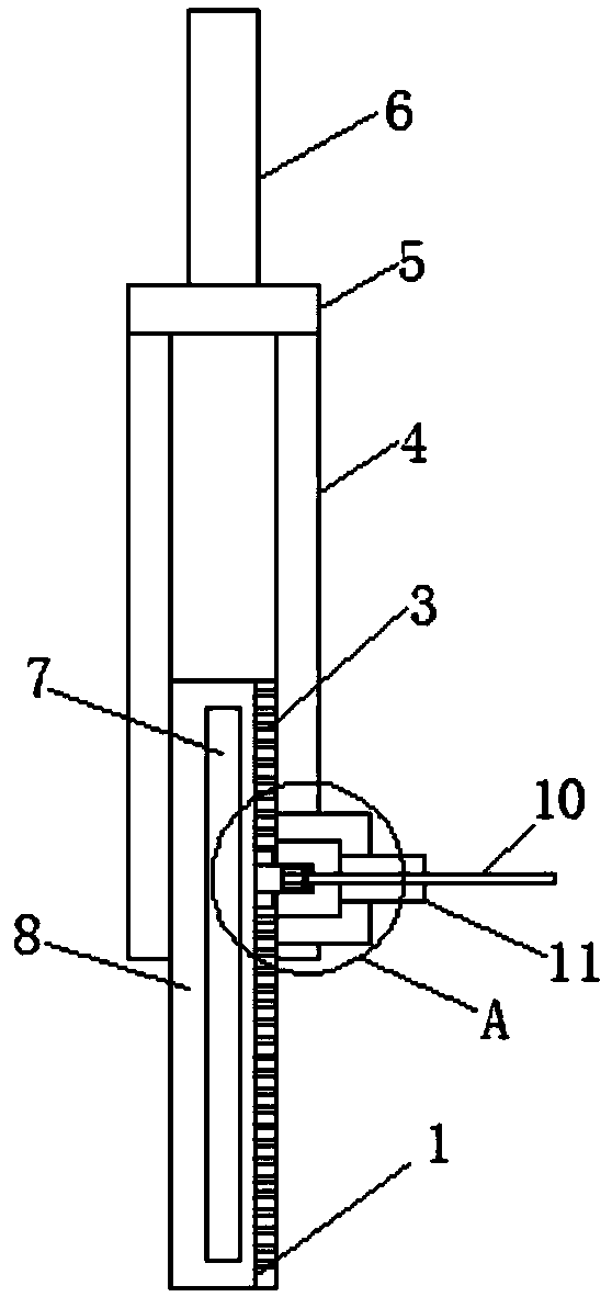
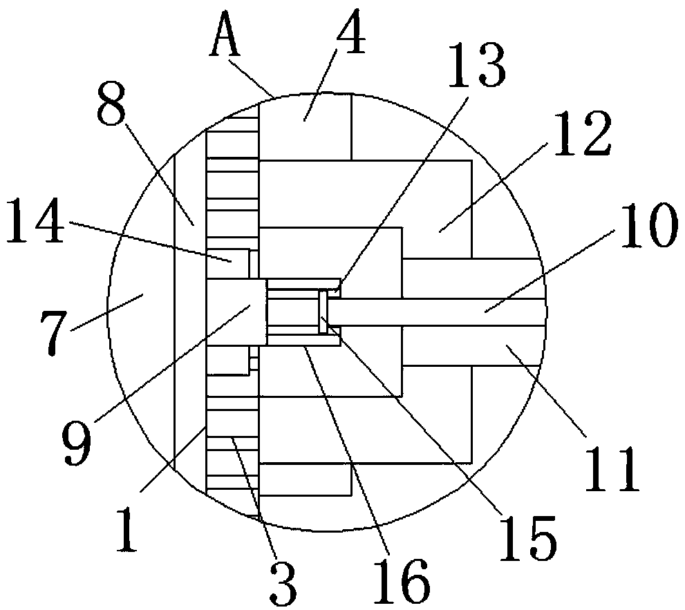
Adjustable transmission shaft
A transmission shaft, adjustable technology, applied in the direction of shafts and bearings, mixers, connecting rods, etc., can solve the problem that the length of the transmission shaft cannot be adjusted, and achieve the effects of simple structure, improved stability, and improved practicability
- Summary
- Abstract
- Description
- Claims
- Application Information
AI Technical Summary
Problems solved by technology
Method used
Image

Examples
Embodiment Construction
[0013] The following will clearly and completely describe the technical solutions in the embodiments of the present invention with reference to the accompanying drawings in the embodiments of the present invention. Obviously, the described embodiments are only some, not all, embodiments of the present invention.
[0014] refer to Figure 1-3 , an adjustable transmission shaft, including a fixed shaft 6, the bottom end of the fixed shaft 6 is provided with a mounting plate 5, the bottom surface of the mounting plate 5 is provided with a first pipe 4, and the bottom end of the first pipe 4 is plugged with a rotating shaft 8. The side of the rotating shaft 8 is provided with a plurality of chute 7, the bottom end of the first pipe 4 is installed with a fixed block 2 corresponding to the position of the chute 7, and one end of the fixed block 2 extends to the inside of the chute 7, so that the chute The side of the groove 7 slides along the side of the fixed block 2. At least two ...
PUM
 Abstract
Description
Claims
Application Information
 - R&D Engineer
- R&D Manager
- IP Professional
- Industry Leading Data Capabilities
- Powerful AI technology
- Patent DNA Extraction
Browse by: Latest US Patents, China's latest patents, Technical Efficacy Thesaurus, Application Domain, Technology Topic, Popular Technical Reports.
© 2024 PatSnap. All rights reserved.Legal|Privacy policy|Modern Slavery Act Transparency Statement|Sitemap|About US| Contact US: help@patsnap.com