Double-head gas stove device and method

A gas stove and gas technology, which is applied to household stoves, heating methods, household stoves/stoves, etc., can solve the problems of easy burns, fires, explosions, and large overflows of plastic products, so as to avoid gas poisoning, ensure safety, The effect of improving safety

Active Publication Date: 2018-12-11
滁州市中诺设备模具制造有限公司
5 Cites 2 Cited by

AI-Extracted Technical Summary

Problems solved by technology

[0002] When people use a double-burner gas stove, they usually use two burners together, which will improve cooking efficiency and save cooking time; when only one burner is used, due to the limited space in the kitchen, people often use the cooking stove The utensils are placed on the hob of another stove, but the hob is very hot after heating, and the plastic items placed on the hob are easily scalded
[0003] In additio...

Abstract

The invention discloses a double-head gas stove device and a method. The double-head gas stove device comprises a gas stove, two detecting plates, infrared sensors, gas sensors, a controller, an alarm, a horizontal guide rail, a support plate, a first cylinder and a support pillar, wherein the two detecting plates are arranged on the gas stove; the infrared sensors and the gas sensors are arrangedon the lower surfaces of the detecting plates; the horizontal guide rail is arranged on a rear lateral plate of the gas stove; the support plate is arranged on the horizontal guide rail; the first cylinder is used for driving the support plate to horizontally move; the support pillar is arranged on the support plate. The double-head gas stove device has the characteristics that a cooking utensilcan be placed on an iron cover plate, the cooking utensil cannot be damaged by burning and the gas source can be timely cut off under the condition that the gas in one stove head is burning but the gas in the other stove head is flowing out and the fire has been extinct.

Application Domain

Domestic stoves or rangesLighting and heating apparatus +2

Technology Topic

Process engineering

Image

  • Double-head gas stove device and method
  • Double-head gas stove device and method
  • Double-head gas stove device and method

Examples

  • Experimental program(2)

Example Embodiment

[0041] Example 1
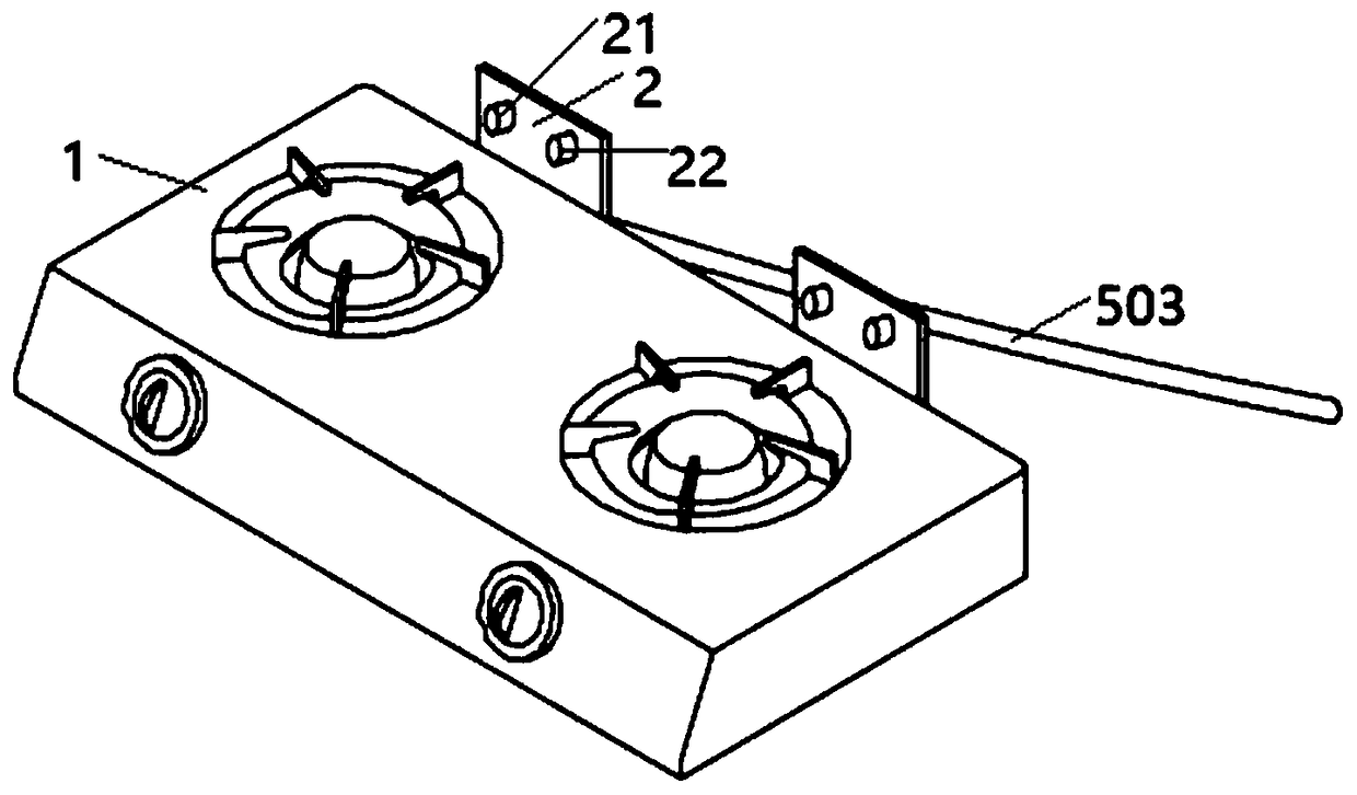
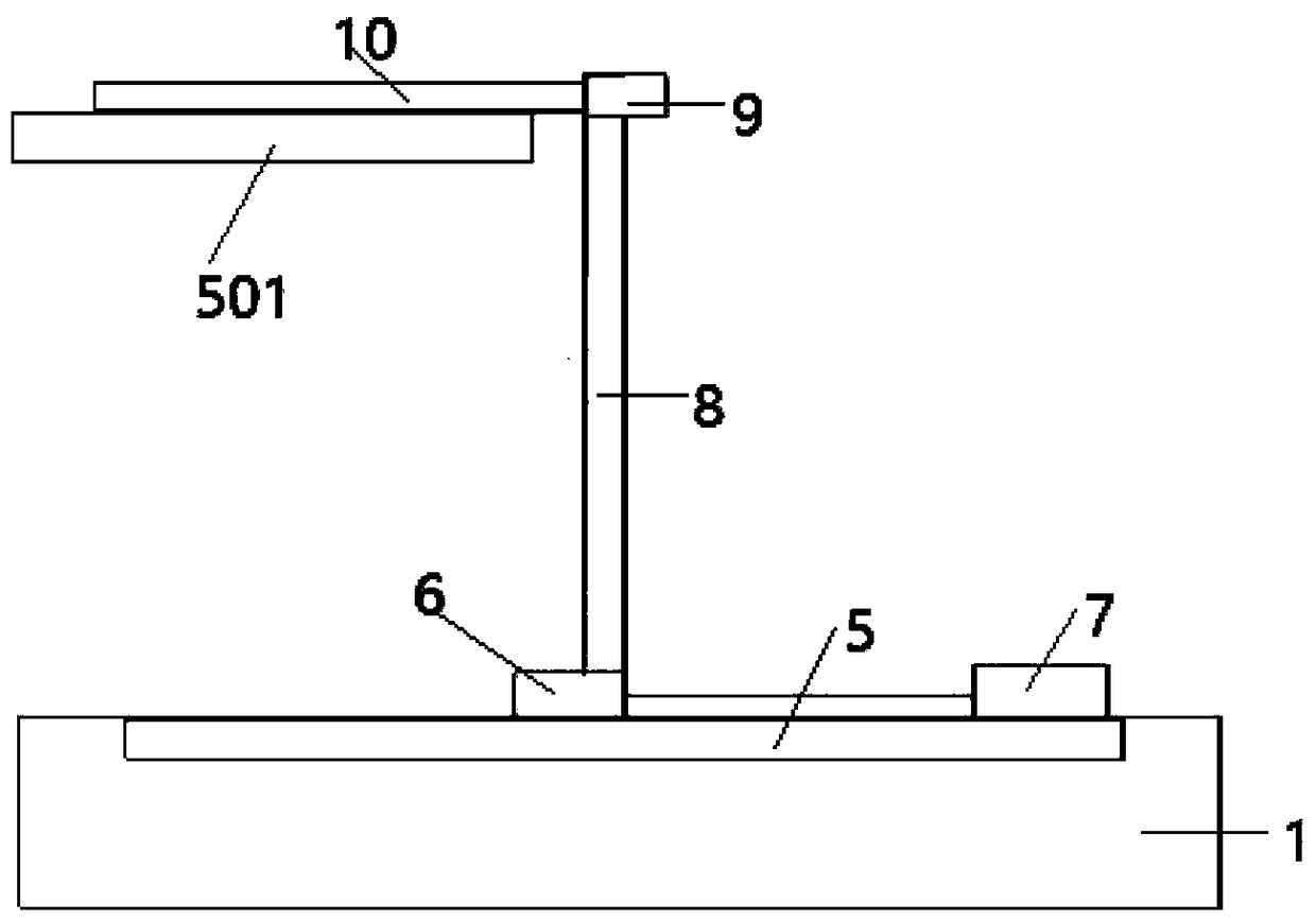
[0042] like figure 1 , figure 2 , Figure 5 The illustrated embodiment is a double-head gas stove device, comprising a gas stove 1, two detection boards 2 arranged on the gas stove, an infrared sensor 21 and a gas sensor 22 arranged on the lower surface of each detection board, and the control 3, the alarm 4, the horizontal guide rail 5 arranged on the rear side plate of the gas range, the support plate 6 arranged on the horizontal guide rail and the first cylinder 7 for driving the support plate to move laterally, the support plate located on the support plate Column 8, the second cylinder 9 located at the upper end of the support column and the horizontal plate 10 connected with the telescopic rod of the second cylinder; the lower surface of the horizontal plate is provided with an iron cover plate 501, and an electromagnet 502 is arranged in the horizontal plate; The cooking range is connected with the intake pipe 503, and the intake pipe is provided with a solenoid valve 504, and the controller is electrically connected with 2 infrared sensors, 2 gas sensors, an alarm, the first cylinder, the second cylinder, an electromagnet and a solenoid valve respectively.
[0043] like Figure 4 As shown, the transverse guide rail includes two cross bars 51 and two longitudinal bars 52, and the two longitudinal bars are respectively located between the left ends of the two cross bars and between the right ends of the two cross bars.
[0044] A method for a double-head gas cooker device, comprising the steps of:
[0045] Step 100, the operator puts the two pots on the hobs of the two burners respectively, controls the electromagnetic valve to open through the controller, and manually turns on the ignition switches of the two burners, and the gas is burned in the two burners respectively;
[0046] Step 200, the two infrared sensors respectively detect the infrared signals in the two burners, and the two gas sensors respectively detect the gas signals in the two burners;
[0047] Both the infrared signal and the gas signal are sent to the controller, and the controller judges the gas combustion of the two burners;
[0048] Step 300, if the gas of one burner is burning, the gas of the other burner stops flowing out and the fire has been extinguished, the controller controls the first cylinder to drive the support plate to move to the top of the extinguished burner;
[0049] The controller controls the second cylinder to drive the horizontal plate to move downward. When the iron cover plate contacts the hob of the burner that has been extinguished, the controller controls the electromagnet to cut off the power, and the magnetic attraction between the iron cover plate and the horizontal plate When the force disappears, the controller controls the second cylinder to drive the horizontal plate to move upward.

Example Embodiment

[0050] Example 2
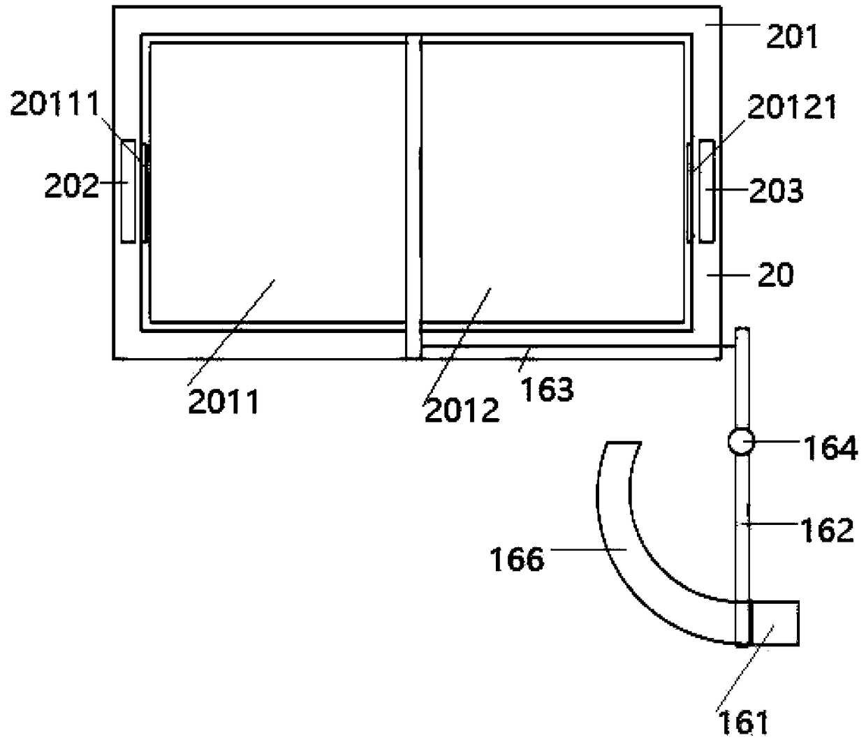
[0051] Embodiment 2 includes all structure and method parts of embodiment 1, such as image 3 Shown, also comprise window 20 and window opening mechanism 16, window comprises window frame 201, the left sash 2011 that is located on the window frame and right sash 2012, window opening mechanism comprises the wall that is located at the window lower right corner of the room where gas range is located The inner air bag 161, the vertical bar 162 that the lower end is connected with one end of the air bag, the rope 163 that is connected with the upper end of the vertical bar, the rope is connected with the lower right corner of the left window sash, and the vertical bar is connected with the wall by the rotating shaft 164, between the upper end of the rotating shaft and the vertical bar The distance between is less than the distance between the rotating shaft and the lower end of the vertical bar, and the ignition switch 165 of the airbag is electrically connected with the controller. An arc-shaped slideway 166 is provided in the wall, and the airbag can extend in an arc-shaped manner along the arc-shaped slideway, and one side of the arc-shaped slideway is provided with an opening matching the swing rod.
[0052] A left permanent magnet 202 is provided in the left part of the window frame, a left iron bar 20111 that cooperates with the left permanent magnet is provided in the left part of the left sash, a right permanent magnet 203 is provided in the right part of the window frame, and a permanent magnet 203 is provided in the right part of the left sash. The right iron bar 20121 that the right permanent magnet cooperates. like Figure 5 As shown, it also includes a fan 505 capable of blowing air out of the window, and the fan is electrically connected to the controller.
[0053] If gas is burning on one burner, gas is flowing out from the other burner and the fire is extinguished; or gas is flowing out from both burners and the fire is extinguished;
[0054] The controller controls the solenoid valve to close, the controller controls the ignition switch of the airbag to ignite, the airbag detonates and expands, the airbag pushes the lower end of the vertical rod to move to the left, the upper end of the vertical rod moves to the right, the vertical rod drives the left window sash to move to the right, and the controller controls the fan Blow the air out of the window.

PUM

no PUM

Description & Claims & Application Information

We can also present the details of the Description, Claims and Application information to help users get a comprehensive understanding of the technical details of the patent, such as background art, summary of invention, brief description of drawings, description of embodiments, and other original content. On the other hand, users can also determine the specific scope of protection of the technology through the list of claims; as well as understand the changes in the life cycle of the technology with the presentation of the patent timeline. Login to view more.

Similar technology patents

Malicious website prompt method and router

ActiveCN104125209Aimprove security
Owner:TENCENT TECH (SHENZHEN) CO LTD +1

Credible virtual machine platform

InactiveCN101957900AImprove stability and attack resistanceimprove security
Owner:706 INST SECOND RES INST OF CHINAAEROSPACE SCI & IND

Intelligent door lock identity authentication method and system, readable storage medium and mobile terminal

ActiveCN109712278APrevent Identity Leakageimprove security
Owner:深圳市小石安防科技有限公司

Classification and recommendation of technical efficacy words

  • prevent further leakage
  • improve security

Gas monitoring and warning protection mechanism

InactiveCN106224633Aprevent further leakage
Owner:东莞市金石电子科技有限公司

Valve capable of being closed automatically

PendingCN109027344Aprevent further leakageAvoid wasting resources
Owner:龙长贵
Why Eureka
Try Eureka