
Ventilation system

A fresh air system and control system technology, applied in ventilation systems, space heating and ventilation, household heating, etc., can solve problems such as unbalanced fresh air supply ratio, independent control of air volume, and damaged beam structure, etc., to increase the utilization of fresh air The effect of air volume, avoiding too large or too small air supply, and flexible installation position

Inactive Publication Date: 2018-12-11
GREE ELECTRIC APPLIANCES INC
View PDF5 Cites 0 Cited by
  • Summary
  • Abstract
  • Description
  • Claims
  • Application Information

AI Technical Summary

Problems solved by technology

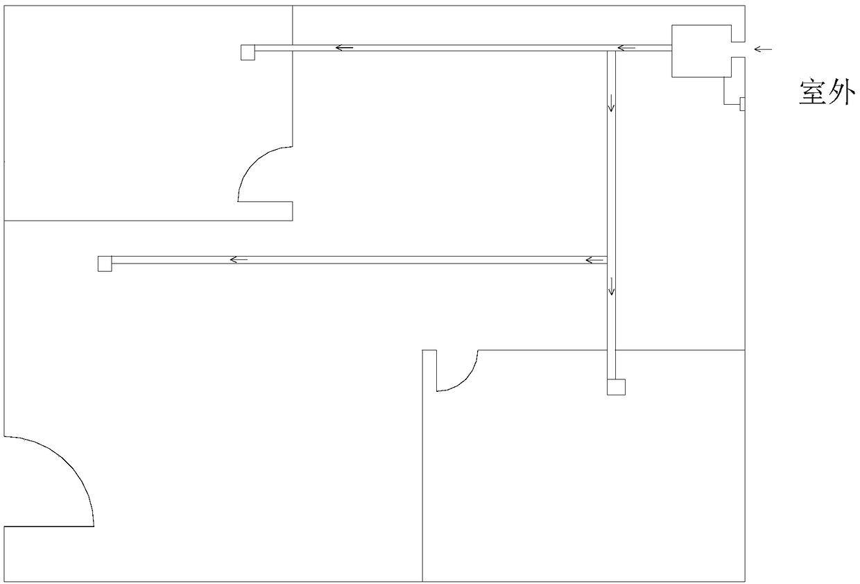
[0002] In recent years, the household fresh air system in our country has been slowly accepted by the public, but the existing fresh air system (such as figure 1 As shown) When it is necessary to send fresh air to the living room, bedroom, dining room and other places of single-family users, it is necessary to install pipes to send the fresh air to the required places. The installation and laying of pipes is not only a large amount of work, but also often needs to be installed through beams , not only will destroy the structure of the beam, but also requires the installation of hidden pipes for ceiling decoration, which adds a lot of difficulty to the decoration design of the house and restricts the cost of decorating the ceiling. The air volume is individually regulated, resulting in the problem of unbalanced fresh air supply ratio and waste of fresh air volume

Method used


Image

  • Ventilation system
  • Ventilation system
  • Ventilation system

Examples


Embodiment Construction

[0018] In order to make the object, technical solution and advantages of the present invention clearer, the present invention will be further described in detail below in conjunction with the accompanying drawings and embodiments. It should be understood that the specific embodiments described here are only used to explain the present invention, not to limit the present invention.

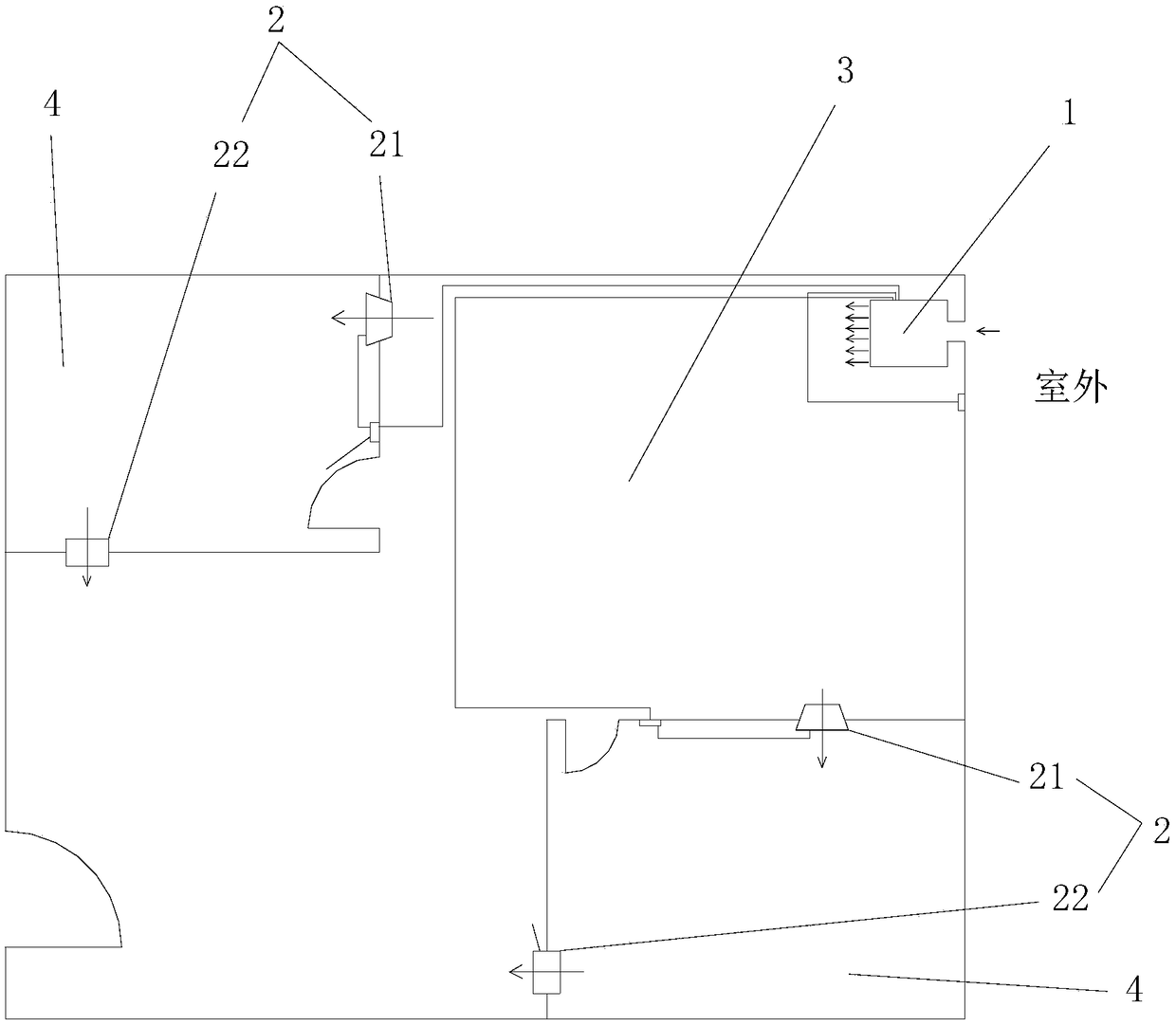
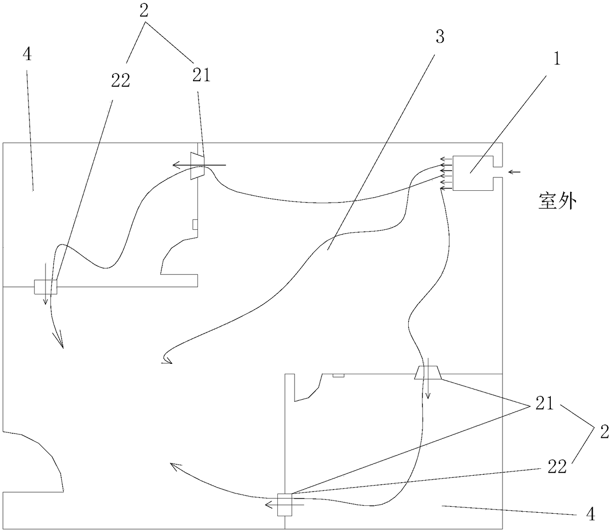
[0019] Such as figure 2 and image 3 The fresh air system shown includes a primary air supply device 1 and at least one secondary air supply device 2, the first end of the primary air supply device 1 communicates with the outside, and the second end communicates with the first room 3, each One end of the secondary air supply device 2 communicates with the first room 3, and the other end communicates with the second room 4. The primary air supply device 1 sends outdoor fresh air to the first room 3 to form the first room. air supply unit, and utilize the secondary air supply device 2 in the air s...


PUM


Abstract

The invention provides a ventilation system, comprising a primary air supply device and at least one secondary air supply device. The first end of the primary air supply device is communicated with the outdoor space; the second end of the primary air supply device is communicated with a first room. The secondary air supply devices are provided in the ventilation system; fresh air can be deliveredto a demanding area without providing pipelines; the problem that multi-point air supply pipelines in an existing ventilation system are difficult to mount is solved. The multiple secondary air supplydevices are controlled independently; air supply quantities for air supply points are under control. All secondary control units are communicated with a primary control unit; air supply quantity of the primary air supply device can be adjusted according to the demands of the secondary air supply devices, fresh air utilization is maximally increased for the ventilation system, and the problem of too high or too low air supply quantity is effectively avoided. An air supply mechanism and an air exhaust mechanism are provided independently; mounting positions are flexible; the ventilation systemis applicable to different housing structures.

Description

technical field [0001] The invention relates to the technical field of air treatment devices, in particular to a fresh air system. Background technique [0002] In recent years, the household fresh air system in our country has been slowly accepted by the public, but the existing fresh air system (such as figure 1 As shown) When it is necessary to send fresh air to the living room, bedroom, dining room and other places of single-family users, it is necessary to install pipes to send the fresh air to the required places. The installation and laying of pipes is not only a large amount of work, but also often needs to be installed through beams , not only will destroy the structure of the beam, but also need the ceiling decoration to hide the installation of the pipeline, which adds a lot of difficulty to the decoration design of the house, and the cost of decorating the ceiling also increases a lot, and the existing fresh air system cannot control each air supply point. The a...

Claims


Application Information

Patent Timeline
Patent Type & Authority Applications(China)
IPC IPC(8): F24F7/007F24F11/74
CPCF24F7/007F24F11/74
Inventor 詹朝永余凯陈文辉杨力
Owner GREE ELECTRIC APPLIANCES INC
Learn More