Engine blade measuring device

A technology of engine blades and measuring devices, which is applied in the direction of mechanical measuring devices, measuring devices, and mechanical devices, etc., can solve the problems of affecting the distance between the intake and exhaust edges, affecting the processing quality of blades, and measuring instability, so as to ensure consistent repeated measurements Sexuality, compact structure, remarkable effect

Inactive Publication Date: 2018-12-11
AECC AVIATION POWER CO LTD
View PDF12 Cites 2 Cited by
  • Summary
  • Abstract
  • Description
  • Claims
  • Application Information

AI Technical Summary

Problems solved by technology

Conventional inlet and exhaust side measuring tools realize the clamping of the tenon by applying force to the bottom surface of the tenon. The size of the pressing force will affect the position of the blade body in the height direction, while the entire edge shape of the inlet and exhaust side belongs to the spatial curve structure. The swing in the height direction will affect the distance from the intake and exhaust edges to the stacking axis, resulting in unstable measurement and poor repeat measurement consistency, thus affecting the processing quality of the entire blade

Method used


Image

  • Engine blade measuring device

Examples


Embodiment Construction

[0019] The present invention will be further described below in conjunction with the accompanying drawings and specific embodiments.

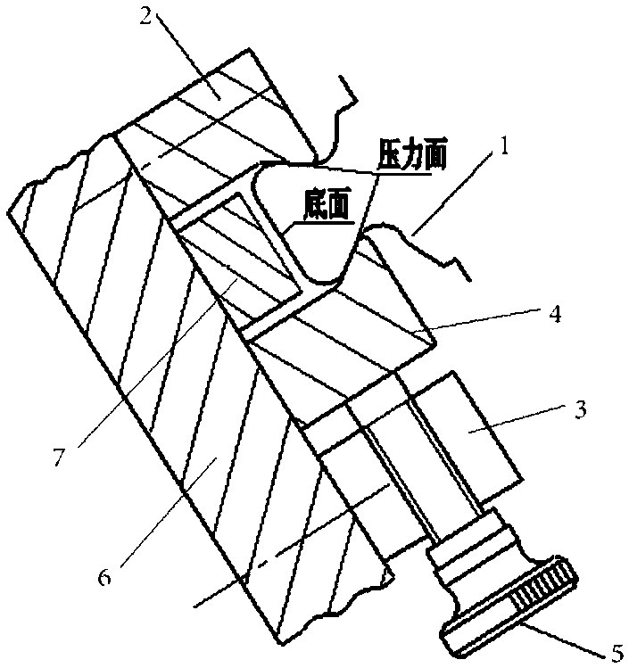
[0020] like figure 1 As shown, the present invention includes a base 6 and a positioning block 2 and a pressing block 4 that are relatively arranged on the base 6, wherein the positioning block 2 is fixedly connected to the base 6, and the pressing block 4 can translate on the base 6 for positioning. The opposite side of the block 2 and the pressing block 4 is provided with a force application surface corresponding to the pressure surface of the blade tenon 1. The structure of the positioning block 2 and the compression block 4 is the same, and the force application surface matches the pressure surface of the blade tenon 1. ; It also includes a support block 7 arranged between the positioning block 2 and the pressing block 4, the top surface of the supporting block 7 is attached to the bottom surface of the blade tenon 1; in addition, the posit...


PUM


Abstract

The invention discloses an engine blade measuring device. The device comprises a blade tenon clamping mechanism, the blade tenon clamping mechanism comprises a pedestal and a positioning block and a compressing block, opposite to the positioning block, arranged on the pedestal, the positioning block is fixedly connected to the pedestal, the compressing block can translate on the pedestal, and theside, opposite to the compressing block, of the positioning block is provided with a force application side corresponding to the pressure surface of a blade tenon; and the compressing block moves towards the positioning block to clamp the blade tenon. Via reasonable structural design, force application to the blade tenon can be controlled more accurately and easier, it is ensured that the bottom of the tenon is butt joint in an aligned way, the blade is avoided for swinging in the height direction, the measuring stability is improved, positions in air inlet and exhaust sides of the blade are measured accurately stably, and the consistency in repeated measurement is higher.

Description

technical field [0001] The invention belongs to the technical field of measuring devices, and in particular relates to a measuring device for engine blades, which is used for measuring the positions of intake and exhaust edges on high-pressure rotor blades of aeroengine compressors. Background technique [0002] At present, the precision-forged blade body of the aviation high-pressure rotor has been finally processed and shaped, and the intake and exhaust edges and tenons have a margin. The processing of the intake and exhaust edges is the focus of the entire blade processing, and the processing of the intake and exhaust edges directly affects the blade shape. Contour. Conventional inlet and exhaust edge measuring tools realize the clamping of the tenon by applying force to the bottom surface of the tenon. The size of the pressing force will affect the position of the blade body in the height direction, while the entire edge shape of the inlet and exhaust edges belongs to th...

Claims


Application Information

Patent Timeline
Patent Type & Authority Applications(China)
IPC IPC(8): G01B21/00
CPCG01B5/0002G01B21/00
Inventor 郭海张义德郭洋许立君郭旭东陈媛媛张静怡杜家燕
Owner AECC AVIATION POWER CO LTD
Why Eureka
Try Eureka