
Accelerometer combined error coefficient separation and calibration method under reference uncertainty condition

A technology of accelerometer and combined error, which is applied in speed/acceleration/shock measurement, testing/calibration of speed/acceleration/shock measurement equipment, and measurement devices, etc., which can solve the influence of frame angle zero offset error and accelerometer calibration error accuracy And other issues

Active Publication Date: 2018-12-11
BEIJING INST OF AEROSPACE CONTROL DEVICES
View PDF11 Cites 7 Cited by
  • Summary
  • Abstract
  • Description
  • Claims
  • Application Information

AI Technical Summary

Problems solved by technology

[0004] The current calibration method for accelerometers under uncertain reference conditions only considers the initial alignment error of the base relative to the geographic coordinate system. For the platform system, there are also frame angle zero offset errors and shaft end non-orthogonal errors. These Error factors also affect the calibration error accuracy of the accelerometer, and these error terms are not involved in the current self-calibration method

Method used


Image

  • Accelerometer combined error coefficient separation and calibration method under reference uncertainty condition
  • Accelerometer combined error coefficient separation and calibration method under reference uncertainty condition
  • Accelerometer combined error coefficient separation and calibration method under reference uncertainty condition

Examples


Embodiment Construction

[0063] This method mainly simplifies the full model of the accelerometer error into a linear simplified model, and separates the error coefficient linearly. At the same time, the error model of the accelerometer comprehensively considers the error of the accelerometer itself and the error of the platform, and can still separate and calibrate the error coefficients of the platform and the accelerometer when the horizontal reference and azimuth reference of the platform are not accurate Come out, reduce the accuracy requirement of the benchmark when the inertial measurement system is calibrated, and improve the calibration accuracy of the error coefficient of the accelerometer.

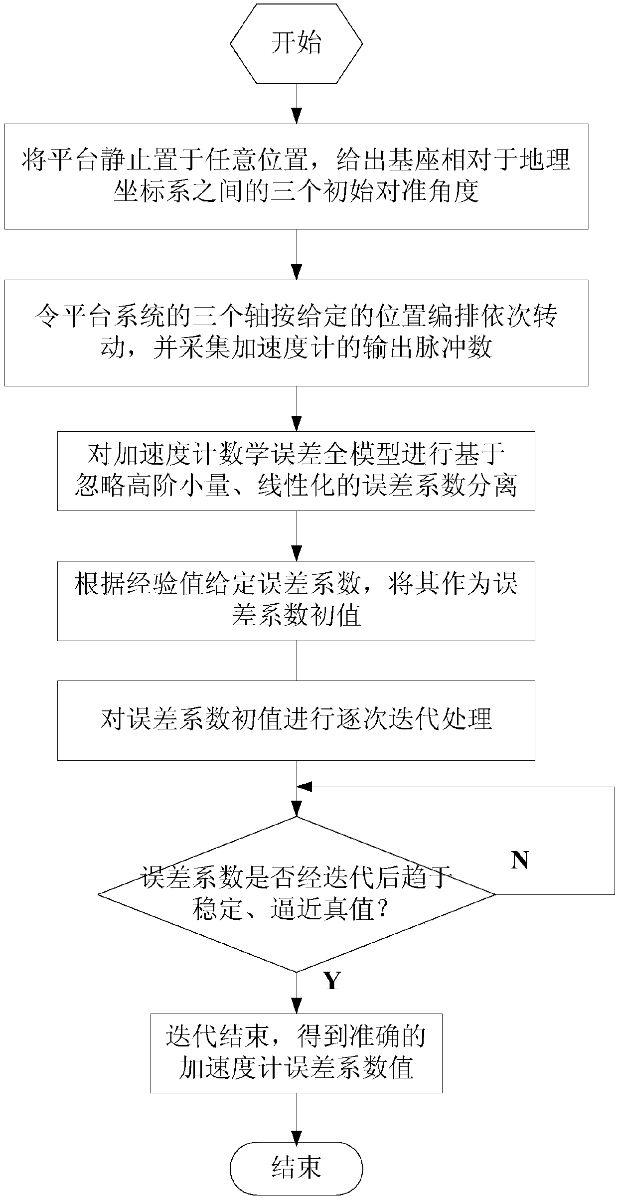
[0064] The test process flow chart of the inventive method is as figure 1 As shown, the specific steps are as follows:

[0065] 1. Put the inertial platform system at a fixed position on the ground, and obtain three initial alignment angles between the platform base and the geographic coordinate system...


PUM


Abstract

The invention relates to an accelerometer combined error coefficient separation and calibration method under a reference uncertainty condition. The method comprises first placing a platform in a certain orientation by establishing a reference mathematical model, rotating the outer frame shaft, the inner frame shaft, and the platform body shaft of the platform in a certain order; measuring the acceleration output pulses along three accelerometer directions; converting the acceleration output pulses into an acceleration output average value; using an error value obtained by performing subtraction on the acceleration output average value and a theoretical calculation value an observation quantity; and substituting a platform azimuth angle and a frame rotation angle, as known quantities, intoa nonlinear acceleration mathematical error model; secondly, separating an error coefficient by using processing methods such as high-order small quantity ignorance, linearization, and iteration; andfinally obtaining the accurate error coefficient, especially the accelerometer error coefficient. In a traditional laboratory calibration method, a base requires a precise orientation reference, whichis not conducive to rapid calibration, or some self-calibration only considers a base orientation error, and has an inaccurate accelerometer error model. The method, by establishing the mathematicalaccurate reference and introducing a platform frame error term, ensures the calibration validity and accuracy of the error coefficient of the platform system, and can also calibrate the accelerometercombined error coefficient under a reference uncertainty condition, thereby improving external field calibration efficiency, and improving the accuracy of a calibration factor.

Description

technical field [0001] The invention relates to a method for calibrating error coefficients, in particular to a method for calibrating error coefficients of accelerometer combinations under uncertain reference conditions, which belongs to platform system calibration technology and can be used to calibrate accelerometer combinations in platform systems. Background technique [0002] Before the inertial system enters work, three important tasks must be performed on it, one of which is error calibration. The error coefficient values ​​of each inertial instrument can be obtained through error calibration, so that they can be compensated in actual operation, thereby improving navigation accuracy. [0003] The general laboratory calibration method is to use laboratory-specific test equipment (high-precision turntable, etc.) for calibration, and use the standard north-facing benchmark and east-facing benchmark as reference benchmarks. However, in actual operation, if the position ...

Claims


Application Information

Patent Timeline
IPC IPC(8): G01P21/00
CPCG01P21/00
Inventor 魏宗康高荣荣
Owner BEIJING INST OF AEROSPACE CONTROL DEVICES
Learn More