Numerical value control device and control method for machine tool

A numerical control device and machine tool technology, which is applied in the direction of digital control, program control, electrical program control, etc., can solve the problems of not considering the flat surface error and the decrease of the judgment accuracy of the tool handle, etc.

Active Publication Date: 2018-12-11
BROTHER KOGYO KK
View PDF6 Cites 2 Cited by
  • Summary
  • Abstract
  • Description
  • Claims
  • Application Information

AI Technical Summary

Problems solved by technology

Therefore, the above-mentioned numerical control device does not consider the error of the flat surface, so there is a possibility that the judgment accuracy of the mounting state of the toolholder may decrease.

Method used


Image

  • Numerical value control device and control method for machine tool
  • Numerical value control device and control method for machine tool
  • Numerical value control device and control method for machine tool

Examples


Embodiment approach 3

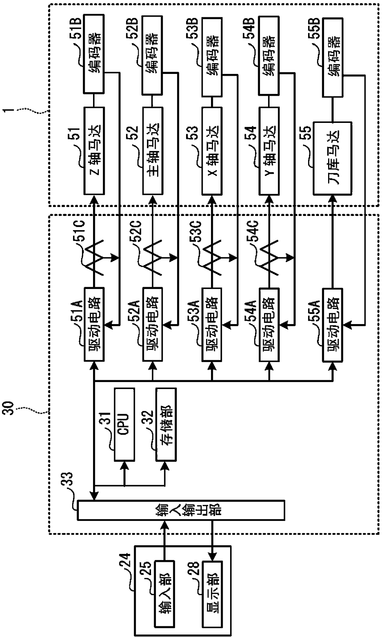
[0090] Numerical controller 30 according to Embodiment 3 can set a more appropriate drive current value by removing high-frequency components from the drive current value using LPF 56 . Therefore, the numerical control device can judge the attachment state of the toolholder with higher accuracy.

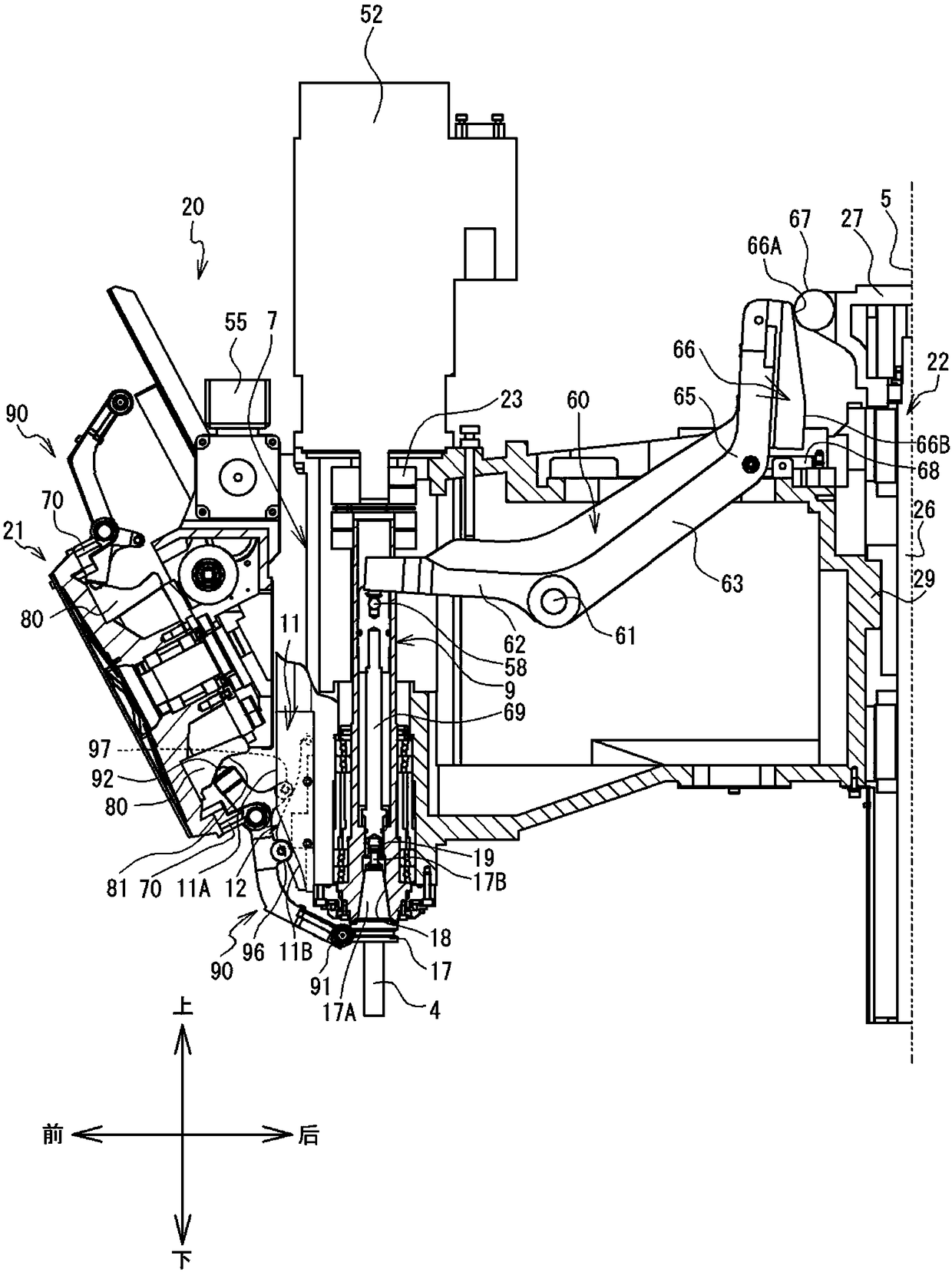
[0091] The present invention is not limited to the above-described embodiments, and various modifications are possible. The cam 66 in the above-described embodiment is fixed to the rod member 60 and supports the roller 67 on the column 5 side. For example, the roller 67 may be supported by the lever member 60 and the cam 66 may be fixed to the column 5 side. In this case, the inclined portion 66A of the cam 66 is inclined from the end portion of the straight portion 66B to the side opposite to the spindle head 7 (the column 5 side).

[0092] The drive circuit 51A to the drive circuit 55A in the above-described embodiment are provided in the numerical controller 30 , but may also be...


PUM


Abstract

The invention relates to a numerical value control device and a control method for a machine tool. A machine tool has a main shaft rotatably arranged at a main shaft head, a pull rod arranged on the main shaft and capable of clamping a knife handle on the main shaft under the function of elastic force of a clamping spring and a loosening operation part, the loosening operation unit has a cam witha cam surface formed by a linear part and an inclined part and a roller in sliding contact with the cam, and the loosening operation part can overcome the elastic force of the clamping spring to release the clamping state of the knife handle relative to the main shaft. The mounting state of the knife handle is judged based on difference between elastic force of the clamping spring in each positionof the main shaft head and elastic force of the clamping spring when the roller and the linear part of the cam are in contact.

Description

technical field [0001] The invention relates to a numerical control device and a control method of a machine tool. Background technique [0002] The machine tool described in Japanese Patent Laid-Open No. 178795 of 2009 includes a spindle head, a cam, rollers, and the like. The spindle head internally supports the spindle in a rotatable manner. The main shaft has a tie rod inside, and the main shaft has a mounting portion for mounting a tool holder at one end. The clamping spring is located on the outer periphery of the pull rod, and exerts force on the pull rod toward the other end. The cam has a substantially trapezoidal shape when viewed from the side, and the cam surface is composed of an inclined surface and a flat surface. The rollers can slide on the cam surfaces. In the machine tool, the roller slides on the cam surface of the cam, and the toolholder is attached and detached from the main shaft. [0003] The numerical control device of the above publication dete...

Claims


Application Information

Patent Timeline
Patent Type & Authority Applications(China)
IPC IPC(8): G05B19/19
CPCG05B19/19G05B2219/35349
Inventor 竹内雅英
Owner BROTHER KOGYO KK
Why Eureka
Try Eureka