Time repair method and device

A repair method and time technology, applied in the direction of generating/distributing signals, etc., can solve problems such as repair failure, ineffective repair time violation, etc., and achieve the effect of improving the scope of application

Active Publication Date: 2018-12-11
SANECHIPS TECH CO LTD
View PDF4 Cites 13 Cited by
  • Summary
  • Abstract
  • Description
  • Claims
  • Application Information

AI Technical Summary

Problems solved by technology

[0005] In order to solve the above technical problems, an embodiment of the present invention provides a time repair method and device to solve the problem that the time repair method

Method used


Image

  • Time repair method and device
  • Time repair method and device
  • Time repair method and device

Examples


Embodiment Construction

[0075] In order to make the purpose, technical solution and advantages of the present invention more clear, the embodiments of the present invention will be described in detail below in conjunction with the accompanying drawings. It should be noted that, in the case of no conflict, the embodiments in the present application and the features in the embodiments can be combined arbitrarily with each other.

[0076] The steps shown in the flowcharts of the figures may be performed in a computer system, such as a set of computer-executable instructions. Also, although a logical order is shown in the flowcharts, in some cases the steps shown or described may be performed in an order different from that shown or described herein.

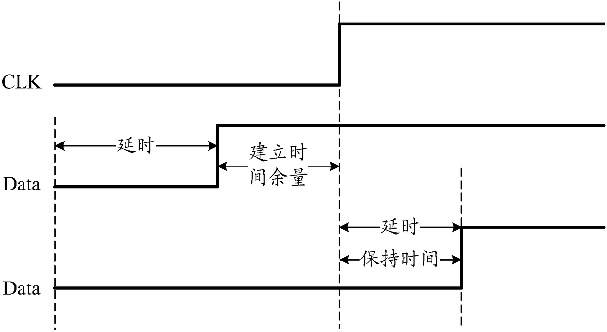
[0077] Before describing the timing repair method provided by the embodiment of the present invention, some basic concepts of timing paths in the circuit are briefly introduced. It has been explained in the background art above that the arrival time of th...


PUM


Abstract

The embodiment of the invention discloses a time repair method and device. The time repair method in the embodiment of the present invention includes a step of determining whether a setup time marginof a current timing path is smaller than a preset margin threshold when a buffer is inserted in the current timing path, wherein the buffer is used for repairing maintenance time violation of the current timing path, and a step of adjusting the setup time window of the current timing path when a condition that the setup time margin is smaller than the preset margin threshold is judged. According to the embodiment of the invention, the problem that a time repair method in the prior art can not effectively repair time violation in some application scenes and thus a repair failure is caused is solved, and thus the application scope of the time repair method is improved.

Description

technical field [0001] The present invention relates to but not limited to the technical field of integrated circuits, in particular to a time repair method and device. Background technique [0002] In chip design, the main design of a digital integrated circuit (Integrated Circuit, IC for short) is the design of a synchronous circuit, and a core device of the synchronous circuit is a register. [0003] When the register is working normally, it is required that the setup time and hold time between the data signal of the register and the clock signal of the register meet certain specifications. That is to say, the setup time and the hold time work together on the register, requiring that the arrival time of the data signal must be in a suitable range relative to the valid edge of the clock signal of the register, neither too early nor too late. If the arrival time of the data signal is too late before the active edge, it will cause a violation of the setup time, so that the ...

Claims


Application Information

Patent Timeline
IPC IPC(8): G06F1/04
CPCG06F1/04
Inventor 王栋
Owner SANECHIPS TECH CO LTD
Why Eureka
Try Eureka