A method and an apparatus for determining wear depth

A technology of wear depth and time, applied in the direction of instruments, geometric CAD, calculation, etc., can solve problems such as insufficient calculation accuracy, and achieve the effect of solving insufficient calculation accuracy

Active Publication Date: 2018-12-11
QINGYAN NEW ENERGY VEHICLE ENG CENT (XIANGYANG) CO LTD
View PDF5 Cites 0 Cited by
  • Summary
  • Abstract
  • Description
  • Claims
  • Application Information

AI Technical Summary

Problems solved by technology

[0003] In view of this, the present application provides a method and device for determining the depth of wear, which is used to solve the problem of insufficient calculation accuracy of the cumulative wear depth of the compound planetary gear transmission system in the prior art

Method used


Image

  • A method and an apparatus for determining wear depth
  • A method and an apparatus for determining wear depth
  • A method and an apparatus for determining wear depth

Examples


no. 1 example

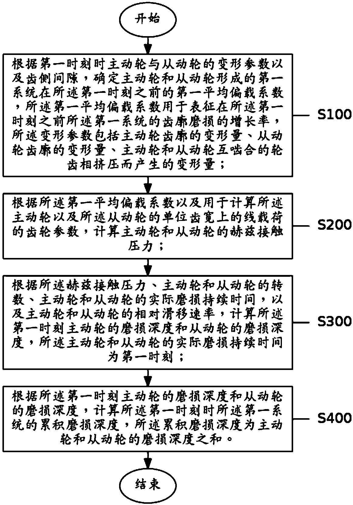
[0026] See figure 1 , figure 1 is a schematic flow chart of the method for determining the wear depth provided by the embodiment of the present application. A method for determining the depth of wear provided by the present application includes:

[0027] Step S100: According to the deformation parameters of the driving wheel and the driven wheel and the tooth backlash at the first moment, determine the first average eccentric load coefficient of the first system formed by the driving wheel and the driven wheel before the first moment, the first An average eccentric load coefficient is used to characterize the growth rate of the tooth profile wear of the first system before the first moment, and the deformation parameters include the deformation amount of the tooth profile of the driving wheel, the deformation amount of the tooth profile of the driven wheel, and the tooth profile of the driving wheel. The amount of deformation caused by the extrusion of the meshing teeth of t...

no. 2 example

[0155] See Figure 10 , Figure 10It is a schematic structural diagram of the device for determining the depth of wear provided by the embodiment of the application; a device for determining the depth of wear 100 provided by the application includes:

[0156] The average eccentric load coefficient determination module 110 is used to determine the first average value of the first system formed by the driving wheel and the driven wheel before the first moment according to the deformation parameters of the driving wheel and the driven wheel and the tooth backlash at the first moment. The eccentric load coefficient, the first average eccentric load coefficient is used to characterize the growth rate of the tooth profile wear of the first system before the first moment, and the deformation parameters include the deformation amount of the driving wheel tooth profile, the driven wheel The amount of deformation of the tooth profile, the amount of deformation caused by the extrusion o...


PUM


Abstract

The present application provides a method and an apparatus for determining wear depth for solving the problem of insufficient calculation accuracy of cumulative wear depth of a compound planetary geartransmission system in the prior art. The method includes: determining a first average bias load coefficient formed by the driving wheel and the driven wheel before the first time according to deformation parameters of the driving wheel and the driven wheel at the first time and tooth side clearance; calculating a Hertz contact pressure of the driving wheel and the driven wheel based on a first average bias load coefficient and gear parameters for calculating a linear load on a unit tooth width of the driving wheel and the driven wheel; calculating the wear depth of the driving wheel and thedriven wheel at the first time according to the Hertz contact pressure, the number of revolutions of the driving wheel and the driven wheel, the actual wear duration of the driving wheel and the driven wheel, and the relative slip rate of the driving wheel and the driven wheel; calculating the cumulative wear depth of the first system at the first time based on the wear depth of the driving wheeland the driven wheel at the first time.

Description

technical field [0001] The present application relates to the technical field of planetary gear transmission, and relates to a method and device for determining wear depth. Background technique [0002] At present, the static calculation method of tooth surface wear is mostly used in the industry. The static calculation method of tooth surface wear means that the growth rate of the target result changes with time. The relationship between the surface pressure and other physical quantities, by calculating the Hertz contact pressure, relative slip rate, wear duration and wear coefficient at each observation point, the distribution of the tooth surface wear of the driving wheel and the driving wheel along the tooth profile direction is obtained law. However, using this static tooth surface wear calculation method to calculate the tooth surface wear of the compound planetary gear has poor load sharing characteristics, which leads to the problem of insufficient calculation accur...

Claims


Application Information

Patent Timeline
IPC IPC(8): G06F17/50
CPCG06F30/17
Inventor 张海波沈小芳
Owner QINGYAN NEW ENERGY VEHICLE ENG CENT (XIANGYANG) CO LTD
Why Eureka
Try Eureka