

Calculation method for electric quantities of battery, device and terminal
A battery power and calculation method technology, applied in the field of communication, can solve problems such as lowering user satisfaction, false alarms, and insufficient power calculation accuracy, and achieve the effect of improving the power calculation accuracy and improving the effect
- Summary
- Abstract
- Description
- Claims
- Application Information
AI Technical Summary
Problems solved by technology
Method used
Image

Examples
Embodiment Construction
[0026] Hereinafter, the present invention will be described in detail with reference to the drawings and examples. It should be noted that, in the case of no conflict, the embodiments in the present application and the features in the embodiments can be combined with each other.
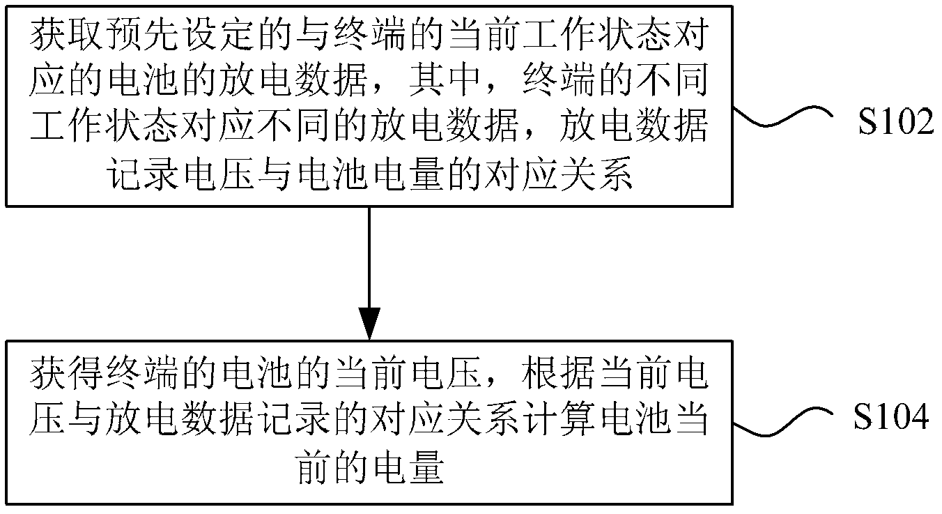
[0027] figure 1 is a flowchart of a method for calculating battery power according to an embodiment of the present invention, such as figure 1 As shown, the method mainly includes the following steps (step S102-step S104):
[0028] Step S102, obtaining preset discharge data of the battery corresponding to the current working state of the terminal, wherein different working states of the terminal correspond to different discharge data, and the discharge data records the corresponding relationship between voltage and battery power;
[0029] In step S104, the current voltage of the battery of the terminal is obtained, and the current battery power is calculated according to the corresponding relations...
PUM
 Abstract
Description
Claims
Application Information