Table tennis ball serving device for sports training
A ball-serving device and technology for sports training, applied in the field of table tennis ball-serving devices for sports training, can solve the problems of complex structure, no height adjustment of the ball-serving device, and difficulty in simulating the opponent's ball-serving mode, etc., and achieve the effect of preventing blockage
- Summary
- Abstract
- Description
- Claims
- Application Information
AI Technical Summary
Problems solved by technology
Method used
Image

Examples
Embodiment 1
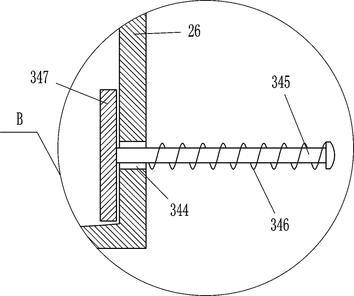
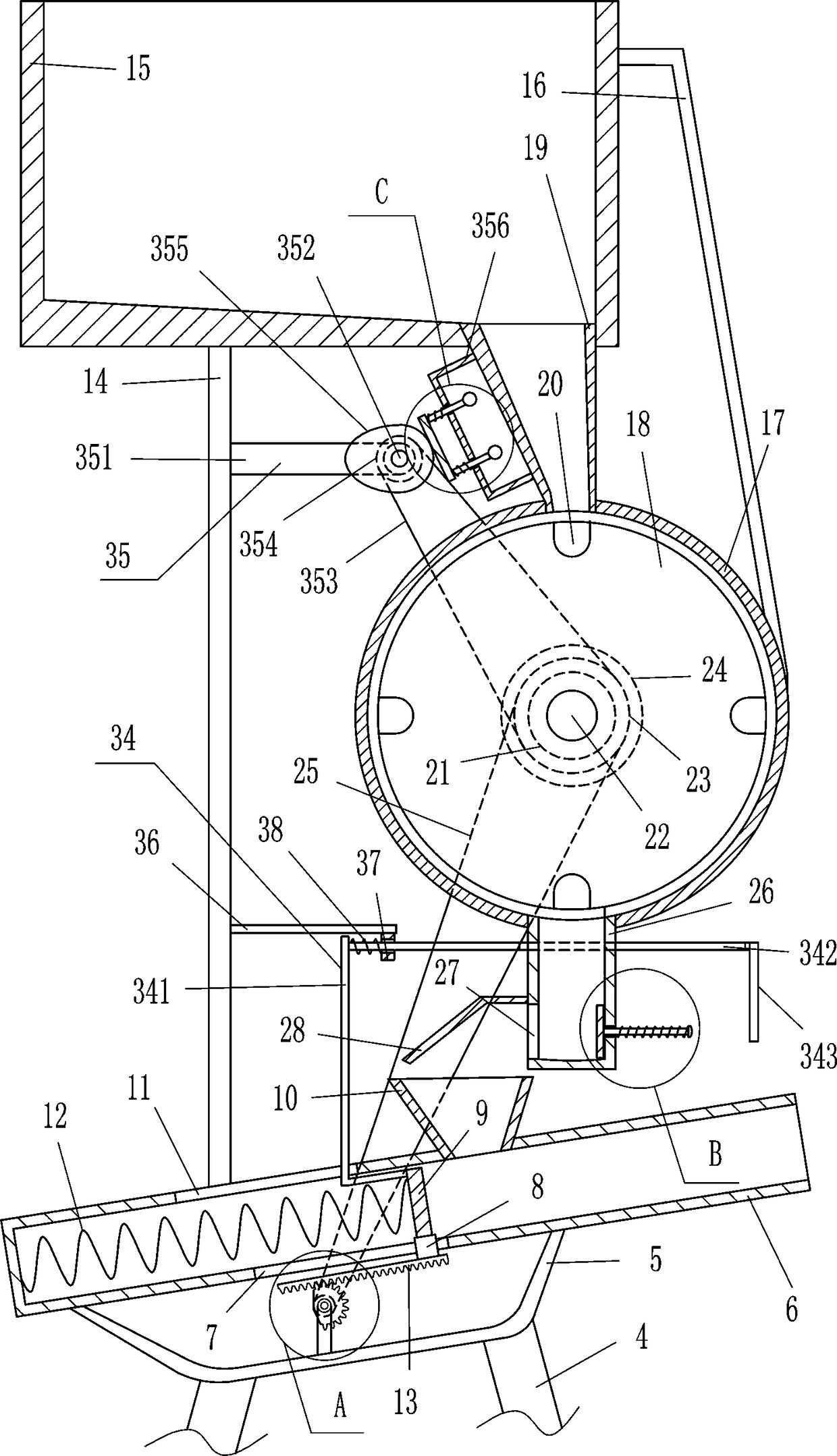
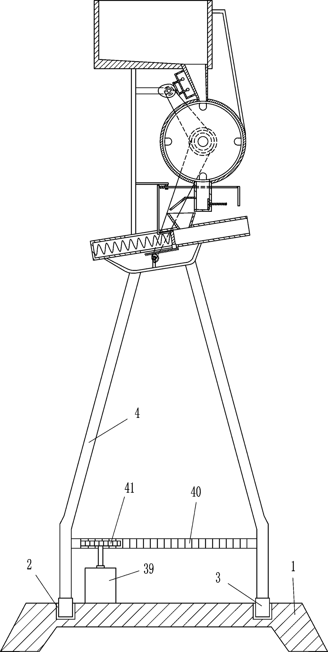
[0023] A kind of table tennis ball serving device for sports training, such as Figure 1-5As shown, it includes a base 1, an annular slider 3, a leg 4, a u-shaped frame 5, a first cylinder 6, a first slider 8, a push plate 9, a feed hopper 10, a first spring 12, a rack 13. Vertical rod 14, placement frame 15, connecting rod 16, second cylinder 17, turntable 18, lower hopper 19, first bearing seat 21, first rotating shaft 22, double groove pulley 23, drive motor 24, first flat Belt 25, frame body 26, baffle plate 28, support rod 29, second bearing seat 30, second rotating shaft 31, first pulley 32 and sector gear 33, there is annular chute 2 in the middle of the top of base 1, annular chute 2 There are two annular sliders 3 inside, and outriggers 4 are installed on the tops of the left and right annular sliders 3, and a u-shaped frame 5 is installed between the tops of the left and right outriggers 4, and between the tops of the left and right sides of the u-shaped frame 5 A f...
Embodiment 2
[0025] A kind of table tennis ball serving device for sports training, such as Figure 1-5 As shown, it includes a base 1, an annular slider 3, a leg 4, a u-shaped frame 5, a first cylinder 6, a first slider 8, a push plate 9, a feed hopper 10, a first spring 12, a rack 13. Vertical rod 14, placement frame 15, connecting rod 16, second cylinder 17, turntable 18, lower hopper 19, first bearing seat 21, first rotating shaft 22, double groove pulley 23, drive motor 24, first flat Belt 25, frame body 26, baffle plate 28, support rod 29, second bearing seat 30, second rotating shaft 31, first pulley 32 and sector gear 33, there is annular chute 2 in the middle of the top of base 1, annular chute 2 There are two annular sliders 3 inside, and outriggers 4 are installed on the tops of the left and right annular sliders 3, and a u-shaped frame 5 is installed between the tops of the left and right outriggers 4, and between the tops of the left and right sides of the u-shaped frame 5 A ...
Embodiment 3
[0028] A kind of table tennis ball serving device for sports training, such as Figure 1-5 As shown, it includes a base 1, an annular slider 3, a leg 4, a u-shaped frame 5, a first cylinder 6, a first slider 8, a push plate 9, a feed hopper 10, a first spring 12, a rack 13. Vertical rod 14, placement frame 15, connecting rod 16, second cylinder 17, turntable 18, lower hopper 19, first bearing seat 21, first rotating shaft 22, double groove pulley 23, drive motor 24, first flat Belt 25, frame body 26, baffle plate 28, support rod 29, second bearing seat 30, second rotating shaft 31, first pulley 32 and sector gear 33, there is annular chute 2 in the middle of the top of base 1, annular chute 2 There are two annular sliders 3 inside, and outriggers 4 are installed on the tops of the left and right annular sliders 3, and a u-shaped frame 5 is installed between the tops of the left and right outriggers 4, and between the tops of the left and right sides of the u-shaped frame 5 A ...
PUM
 Abstract
Description
Claims
Application Information
PatSnap Eureka turns technology decisions into work you can execute. Powered by our Innovation Knowledge Graph, it runs expert workflows across engineering, life sciences, materials and intellectual property. Get your review-ready output in minutes.


