Supercharge Your Innovation With Domain-Expert AI Agents!

Method and device for detecting degradation of optical module

A detection method and optical module technology, applied in the field of optical communication, can solve problems such as the inability of the optical module to diagnose its own performance, the deterioration of the optical module, etc., to achieve the effect of providing fault handling efficiency, preventing business anomalies, and facilitating and rapid positioning

Active Publication Date: 2021-03-02
HISENSE BROADBAND MULTIMEDIA TECH
View PDF10 Cites 0 Cited by
  • Summary
  • Abstract
  • Description
  • Claims
  • Application Information

AI Technical Summary

Problems solved by technology

[0005] This application provides a method and device for detecting the degradation of an optical module to solve the problem that the optical module cannot diagnose its own performance in the prior art

Method used


Image

  • Method and device for detecting degradation of optical module
  • Method and device for detecting degradation of optical module
  • Method and device for detecting degradation of optical module

Examples


Embodiment Construction

[0025] In order to enable those skilled in the art to better understand the technical solutions in the present invention, the technical solutions in the embodiments of the present invention will be clearly and completely described below in conjunction with the drawings in the embodiments of the present application. Obviously, the described The embodiments are only some of the embodiments of the present invention, not all of them. Based on the embodiments in this application, all other embodiments obtained by persons of ordinary skill in the art without creative efforts shall fall within the protection scope of the present invention.

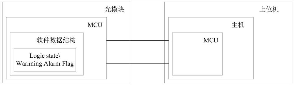
[0026] see figure 1 , is a schematic diagram of communication between the optical module and the host computer in the prior art. like figure 1 As shown, in the optical communication system, the host computer communicates with the optical module to realize the conversion between optical and electrical signals. The host computer in the upper com...


PUM


Abstract

The application discloses a method and device for detecting degradation of an optical module, which relates to the field of optical communication technology and is invented to solve the problem that the optical module cannot diagnose its own performance in the prior art. The method of the present application mainly includes: obtaining the actual working temperature and the actual driving current of the optical module; calculating according to the actual working temperature, the actual driving current and the preset value to obtain the error value of the driving current; writing the error value into the memory The preset position can be read by the host computer. This application is mainly applied in the process of using the optical module for communication.

Description

technical field [0001] The present application relates to the technical field of optical communication, in particular to a method and device for detecting degradation of an optical module. Background technique [0002] see figure 1 , is a schematic diagram of communication between the optical module and the host computer in the prior art. like figure 1 As shown, in the optical communication system, the host computer communicates with the optical module to realize the conversion between optical and electrical signals. The host computer in the upper computer acts as a communication host and can access multiple optical modules, and the optical module acts as a communication slave, and the optical module can only accept read and write operations from the host. When the optical module MCU detects that its own state is abnormal or triggers an alarm threshold, it will update the value of the above storage address. When the host MCU accesses the address of the slave optical modu...

Claims


Application Information

Patent Timeline
Patent Type & Authority Patents(China)
IPC IPC(8): G01M11/00G01R31/00
CPCG01M11/00G01R31/00
Inventor 崔涛
Owner HISENSE BROADBAND MULTIMEDIA TECH
Features
  • R&D
  • Intellectual Property
  • Life Sciences
  • Materials
  • Tech Scout
  • Unparalleled Data Quality
  • Higher Quality Content
  • 60% Fewer Hallucinations
Learn More