A delay lighting switch for corridor street lamps

A technology for lighting switches and street lamps, which is applied in the direction of lighting devices, lamp circuit layout, light sources, etc., and can solve problems such as increasing installation costs, affecting residents going downstairs, and affecting residents going upstairs

Pending Publication Date: 2018-12-14
温悦廷
View PDF0 Cites 0 Cited by
  • Summary
  • Abstract
  • Description
  • Claims
  • Application Information

AI Technical Summary

Problems solved by technology

[0008] However, when the existing time-delay lighting switch is actually installed, such as figure 2 As shown, regardless of the touch switch or the voice-activated switch, it is usually installed at the door of the residents on each floor, so that the residents can open the door to turn on the road lights on the floor (for the touch switch, it is convenient for the residents to touch and open, and for the voice-activated switch, it is also easy to sense the sound from the residents. Turn on the road lights in time)
However, in this installation method, the lighting coverage of the floor street lights can only be the upper and lower half floors (such as figure 2 Shown upper half layer A, lower half layer B), for the lower half layer of the upper layer (such as figure 2 Shown lower half floor C), then can't cover, like this, when the user goes up to the lower half floor of the upper floor, can't see the stairs clearly, influences the resident to go upstairs; Similarly, for the upper half floor of the next floor (not drawn), also cannot be covered, so that when the user goes down to the upper half of the next floor, he will not be able to see the stairs clearly, which will affect the residents going downstairs
[0009] If you install time-delay lighting switches on the upper and lower half floors, the above problems can be solved, but this will increase the installation cost, especially in today's very high labor costs
At the same time, for traditional old communities, it is more troublesome to carry out line reconstruction

Method used


Image

  • A delay lighting switch for corridor street lamps
  • A delay lighting switch for corridor street lamps
  • A delay lighting switch for corridor street lamps

Examples


Embodiment Construction

[0030] Specific embodiments of the present invention will be described below in conjunction with the accompanying drawings, so that those skilled in the art can better understand the present invention. It should be noted that in the following description, when detailed descriptions of known functions and designs may dilute the main content of the present invention, these descriptions will be omitted here.

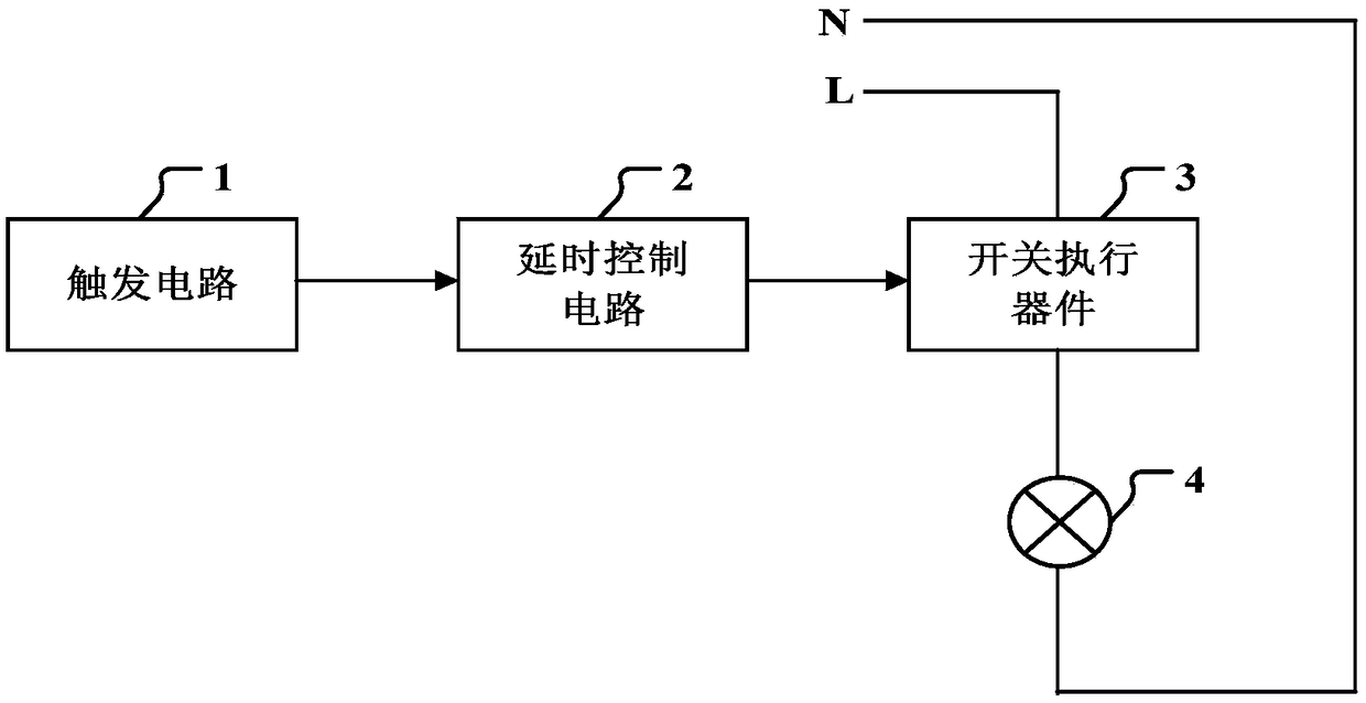
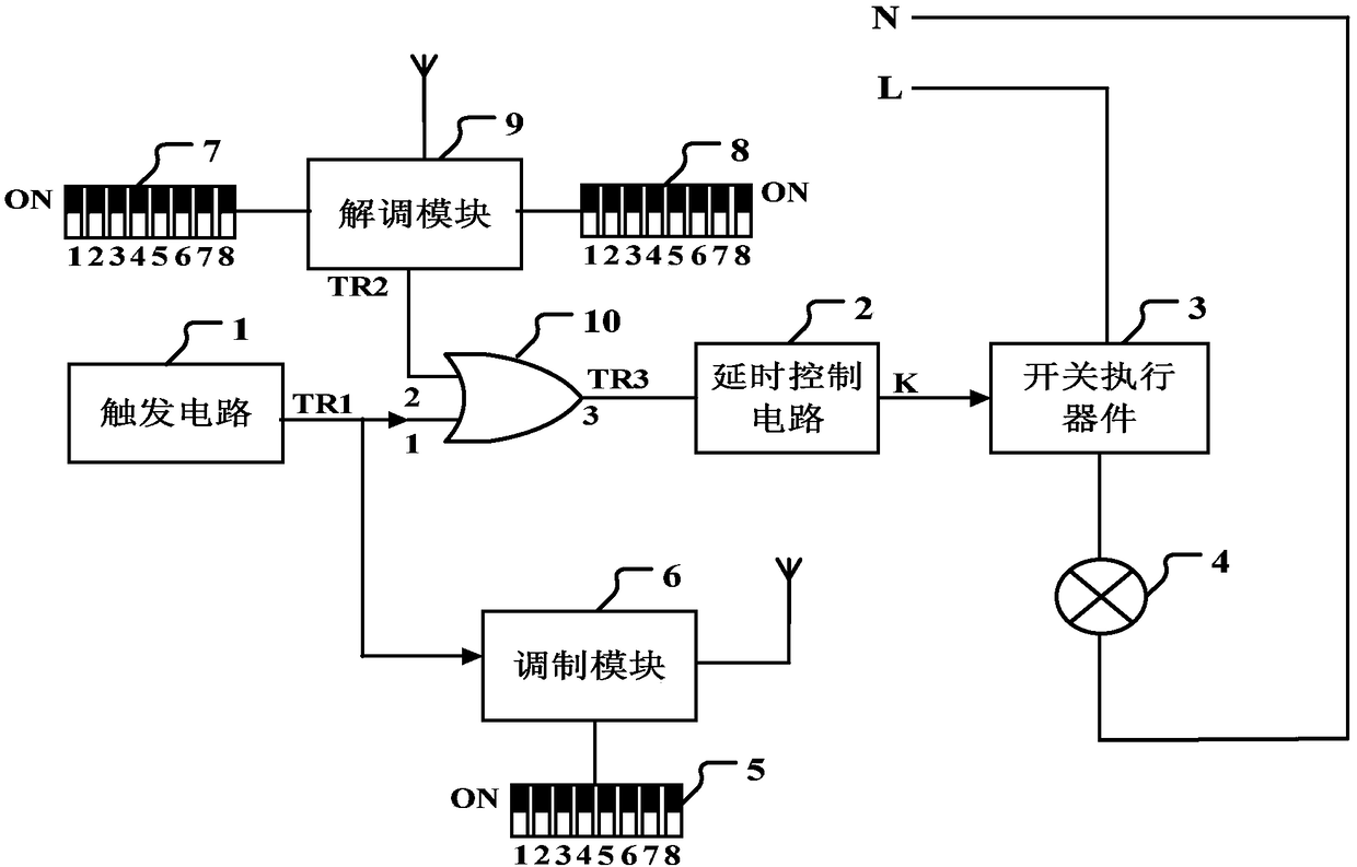
[0031] image 3 It is a principle block diagram of the time-delay lighting switch used for building road lamps in the present invention.

[0032] In this example, if image 3 As shown, the present invention is used for the time-delayed lighting switch of the floor road lamp, which is characterized in that it includes: a trigger circuit 1, a time-delay control circuit 2, a switch actuator 3, and a floor dial switch 5 added on this basis, a modulation Module 6, DIP switch 7 on the upper layer, DIP switch 8 on the lower layer, demodulation module 9, or gate 10.

[0033] The...


PUM


Abstract

The invention discloses a delay lighting switch for corridor street lamps, which comprises a floor dialing switch, a modulating module, an upper-floor dialing switch, a lower-floor dialing switch, a demodulating module and an OR door on the basis of the prior art. When the first trigger signal outputted from the trigger circuit arrives, Read by Modulation Module, and modulated on the carrier wave,the delay lighting switches installed on the upper floor and the lower floor receive the modulated signal, demodulates the number of floors of the installed floor, and then compares the number of floors set by the code dialing switch on the next floor and the code dialing switch on the upper floor. At this time, the delay control circuit is triggered by outputting the second triggering signal, sothat the street lamps on the upper floor and the lower floor are turned on. In this way, the lighting problem of the lower half of the upper floor and the upper half of the lower floor of the corridor is solved, thereby facilitating the residents to go up and down the stairs.

Description

technical field [0001] The invention belongs to the technical field of street lamp control, and more specifically relates to a time-delayed lighting switch for building street lamps. Background technique [0002] A switch with a delayed lighting control function is called a delayed lighting switch. Time-delay lighting switch (referred to as time-delay switch) is a new type of automatic time-delay electronic switch developed to save power resources, which is power-saving and convenient. The time-delay lighting switch makes the light source (lamp) turned on, and after a period of delay, the light source is automatically turned off. Delayed lighting switches are mostly used in places that do not require long-term lighting such as stairs, corridors, halls, and toilets. Using this switch can not only prevent people from forgetting to turn off the lights and cause power waste, but also prolong the service life of the light source (light). [0003] In terms of trigger mode, the d...

Claims


Application Information

Patent Timeline
IPC IPC(8): H05B37/02
CPCH05B47/16Y02B20/40
Inventor 温悦廷
Owner 温悦廷
Why Eureka
Try Eureka