Rotatable sliding front supporting device for bending machine

A bending machine and rotary technology, applied in the field of bending machines, can solve the problems of inability to meet the requirements of machining accuracy, poor positioning accuracy, complicated operation, etc., and achieve the effects of good promotion and use value, convenient use and stable structure

Pending Publication Date: 2018-12-18
山东嘉意机械有限公司
View PDF0 Cites 0 Cited by
  • Summary
  • Abstract
  • Description
  • Claims
  • Application Information

AI Technical Summary

Problems solved by technology

[0005] The technical task of the present invention is to address the above deficiencies and provide a rotatable sliding front support device for a bending machine, which can solve the problem of low freedom, poor positioning accuracy and cumbersome operation of the front support device of a traditional bending machine in the prior art. Problems that cannot meet the requirements of modern machining accuracy

Method used


Image

  • Rotatable sliding front supporting device for bending machine
  • Rotatable sliding front supporting device for bending machine
  • Rotatable sliding front supporting device for bending machine

Examples


Embodiment 1

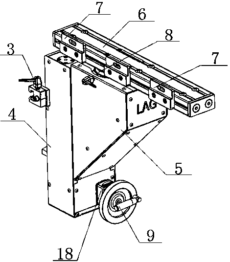
[0032] The rotatable sliding front supporting device for bending machine of the present invention includes a frame, a front and rear sliding device, a lifting drive device and a material supporting device, and the front and rear sliding device includes a slider seat 1, a fixed slide rail 2 and a locking clamp 3. The fixed slide rail 2 is fixed on the bending machine through bolts, the slider seat 1 is set on the fixed slide rail 2 and can slide on the fixed slide rail 2; the slider seat 1 is fixed on the side wall of the frame, and the lock The clamping block 3 is movably arranged on the fixed slide rail 2; the frame includes a fixed frame 4 and a mobile frame 5, the lifting drive device is arranged in the fixed frame 4, and the supporting device is arranged above the mobile frame 5;

[0033] The material supporting device comprises a material supporting slide rail 6 and a rear baffle 7, and two rear baffle plates 7 are arranged on the outside of the material supporting slide r...

Embodiment 2

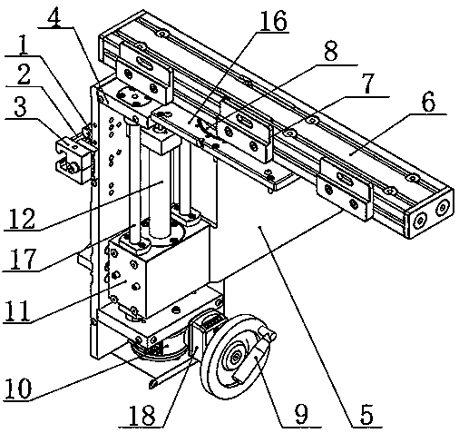
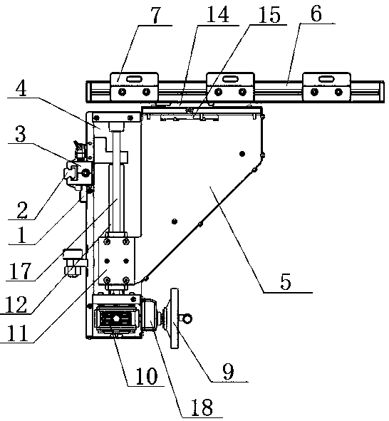
[0037] The rotatable sliding front supporting device for bending machine of the present invention includes a frame, a front and rear sliding device, a lifting drive device and a material supporting device, and the front and rear sliding device includes a slider seat 1, a fixed slide rail 2 and a locking clamp 3. The fixed slide rail 2 is fixed on the bending machine through bolts, the slider seat 1 is set on the fixed slide rail 2 and can slide on the fixed slide rail 2; the slider seat 1 is fixed on the side wall of the frame, and the lock The clamping block 3 is movably arranged on the fixed slide rail 2; the frame includes a rectangular frame structure fixed frame 4 and a triangular frame structure mobile frame 5, the lifting drive device is arranged in the fixed frame 4, and the supporting device is arranged on the mobile machine above shelf 5;

[0038] The material supporting device comprises a material supporting slide rail 6 and a rear baffle 7, two sliding blocks 13 ar...


PUM


Abstract

The invention discloses a rotatable sliding front supporting device for a bending machine, belongs to the technical field of bending machines, and the problems that in the prior art, the front supporting device of a traditional bending machine is low in degree of freedom, poor in positioning precision and complex in operation and cannot meet the requirement of modern machining precision are solved. According to the technical scheme, the rotatable sliding front supporting device comprises machine frames, a front-back sliding device, a lifting driving device, a rotating device and a material supporting device, wherein the machine frames comprise a fixed machine frame and a movable machine frame, the lifting driving device is arranged in the fixed machine frame, and the material supporting device is arranged above the movable machine frame; the material supporting device comprises a material supporting sliding rail and rear material blocking plates, the multiple rear material blocking plates are arranged on the outer side of the material supporting sliding rail and can slide on the material supporting sliding rail; and the rotating device is arranged between the material supporting sliding rail and an upper top plate of the movable machine frame, the rotating device comprises a rotary table, a long hole penetrating through the material supporting sliding rail is formed in the material supporting sliding rail, and a bolt penetrates through the long hole to enable the material supporting sliding rail to be fixedly connected with the rotary table.

Description

technical field [0001] The invention relates to the technical field of bending machines, in particular to a rotatable sliding front material support device for bending machines. Background technique [0002] A bending machine is a mechanical device capable of bending thin plates. The structure of a common bending machine usually includes a bracket, a workbench and a clamping plate. The workbench is placed on the bracket. The workbench is composed of a base and a pressure plate. Connected with the clamping plate, the base is composed of a seat shell, a coil and a cover plate, the coil is placed in the recess of the seat shell, and the top of the recess is covered with a cover plate. When in use, the wire is energized to the coil, and after energization, an attractive force is generated on the pressure plate, so as to realize the clamping of the thin plate between the pressure plate and the base. Due to the use of electromagnetic force clamping, the pressure plate can be made...

Claims


Application Information

Patent Timeline
IPC IPC(8): B21D43/00B21D5/00
CPCB21D5/00B21D43/00
Inventor 乔荣旺王春霞沈伟虞敬淼
Owner 山东嘉意机械有限公司
Why Eureka
Try Eureka