
Cutting device

A technology of cutting device and cutting end, which is applied in the direction of shearing device, attachment device of shearing machine, shearing machine equipment, etc., can solve the problems of large volume of cutting equipment, occupy a lot of space, and low cutting precision, and achieve compact structure and space occupation Less, the effect of improving hobbing precision

Pending Publication Date: 2018-12-18
WUXI LEAD INTELLIGENT EQUIP CO LTD
View PDF9 Cites 1 Cited by
  • Summary
  • Abstract
  • Description
  • Claims
  • Application Information

AI Technical Summary

Problems solved by technology

In the prior art, a knife is used for cutting, resulting in a large volume of cutting equipment, a lot of space, high cost, and low cutting accuracy.

Method used


Image

  • Cutting device
  • Cutting device
  • Cutting device

Examples


Embodiment Construction

[0056] The technical solutions of the present invention will be clearly and completely described below in conjunction with the accompanying drawings. Apparently, the described embodiments are some of the embodiments of the present invention, but not all of them. Based on the embodiments of the present invention, all other embodiments obtained by persons of ordinary skill in the art without making creative efforts belong to the protection scope of the present invention.

[0057] In the description of the present invention, it should be noted that the terms "center", "upper", "lower", "left", "right", "vertical", "horizontal", "inner", "outer" etc. The indicated orientation or positional relationship is based on the orientation or positional relationship shown in the drawings, and is only for the convenience of describing the present invention and simplifying the description, rather than indicating or implying that the referred device or element must have a specific orientation, ...


PUM


Abstract

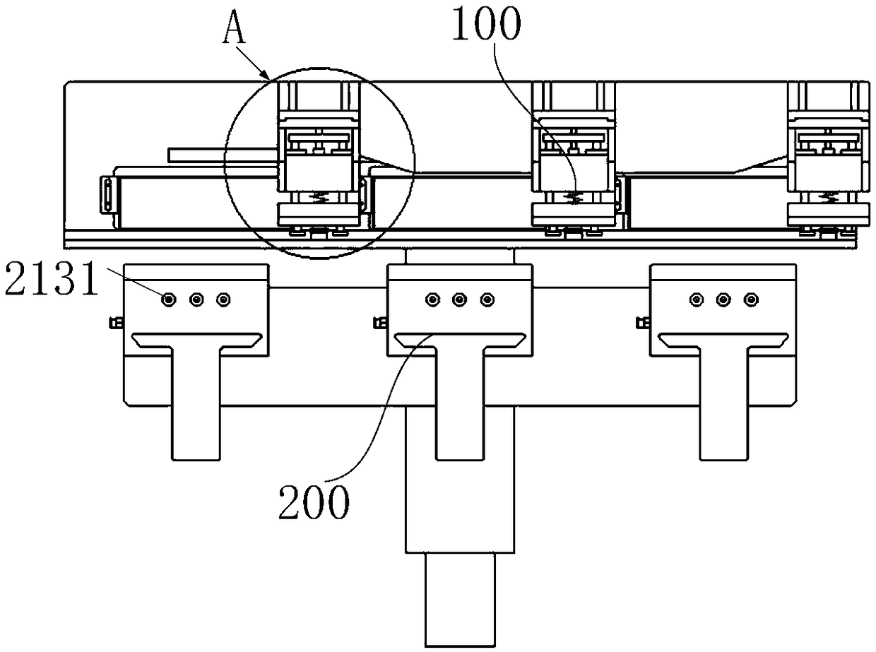
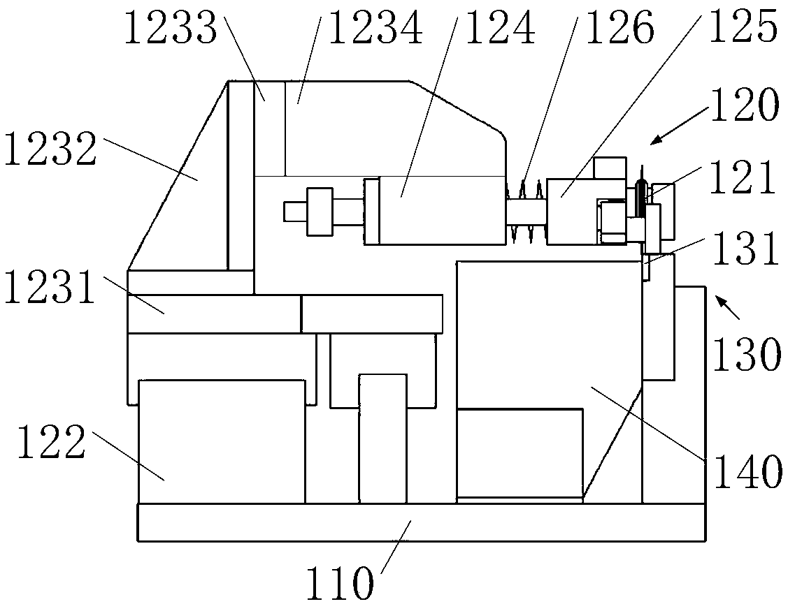
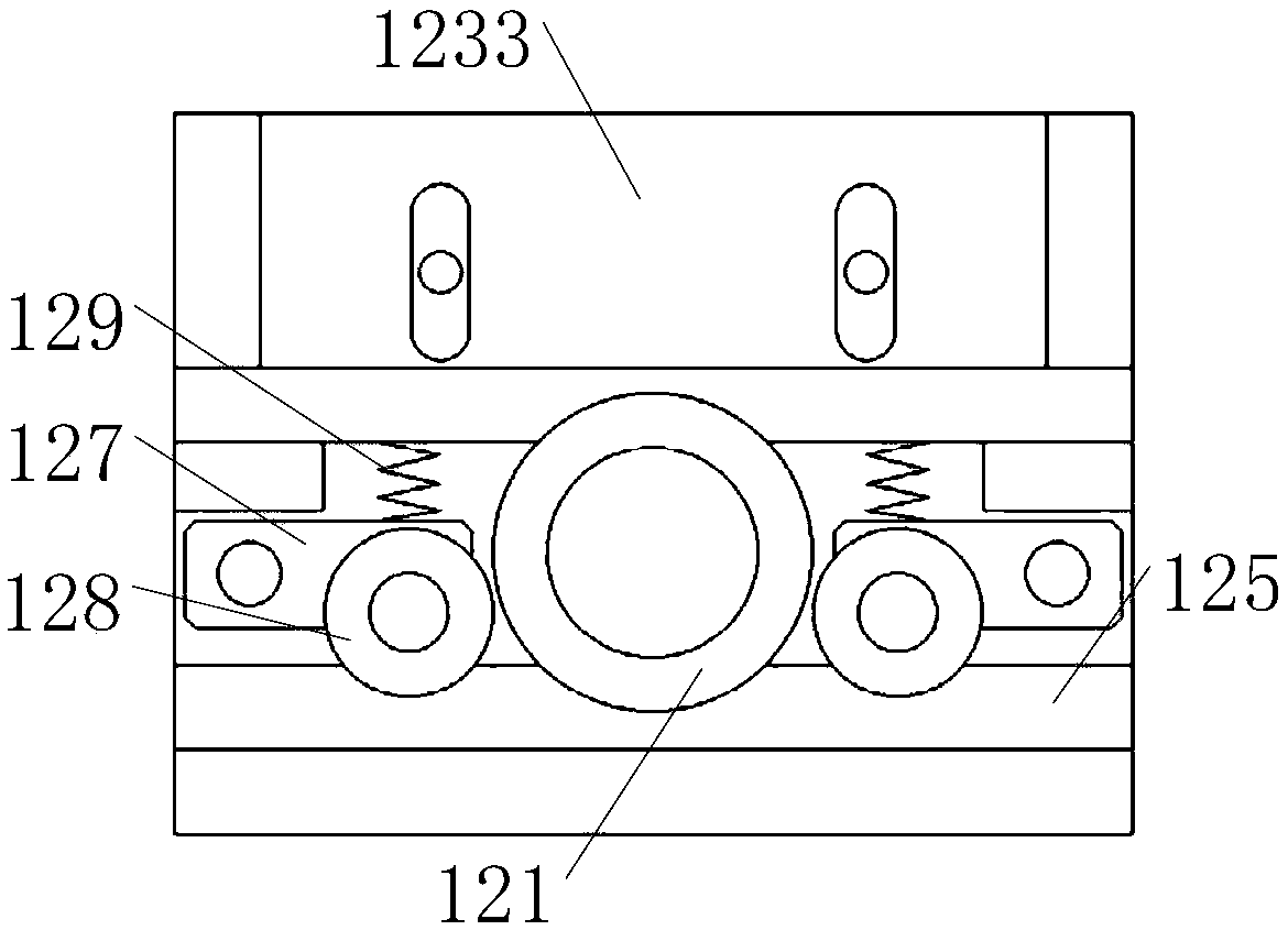
The invention provides a cutting device, and relates to the technical field of battery manufacture devices. The cutting device comprises a roll-cutting mechanism and a positioning mechanism. A soft package battery is arranged on the positioning mechanism and is positioned through the positioning mechanism. The roll-cutting mechanism can cut a gas bag of the positioned soft package battery. The cutting device solves the problems that in the prior art, a cutting device is loose in layout, large in occupied space, low in cutting precision and the like.

Description

technical field [0001] The invention relates to the technical field of battery manufacturing equipment, in particular to a cutting device. Background technique [0002] During the manufacturing process of the pouch battery, it is necessary to cut off the air pocket opening of the pouch battery to ensure that the air pocket opening of the pouch battery is flush. In the prior art, a switch knife is used for cutting, resulting in a large volume of cutting equipment, a large space occupation, high cost, and low cutting precision. [0003] Based on the above problems, it is particularly important to propose a cutting device with a compact structure and high cutting precision. [0004] The information disclosed in this Background section is only intended to enhance the understanding of the general background of the present invention, and should not be considered as an acknowledgment or any form of suggestion that the information constitutes the prior art that is already known to ...

Claims


Application Information

Patent Timeline
IPC IPC(8): B23D19/04B23D33/02
CPCB23D19/04B23D33/02
Inventor 不公告发明人
Owner WUXI LEAD INTELLIGENT EQUIP CO LTD
Learn More