
Material flow-dividing device for plastic mould

A technology of a shunt device and a plastic mold, applied in the field of plastic molds, can solve the problems of a single structure of the shunt device, increase the strength of the work, reduce the efficiency of the work, etc., and achieve the effect of facilitating the work, reducing the strength and shortening the time.

Inactive Publication Date: 2018-12-18
李澎
View PDF2 Cites 0 Cited by
  • Summary
  • Abstract
  • Description
  • Claims
  • Application Information

AI Technical Summary

Problems solved by technology

[0003] In view of this, the embodiment of the present invention provides a material diversion device for plastic molds to improve the existing diversion equipment with a single structure. When in use, the diversion process is performed through valves, which causes great inconvenience to users. Increase the intensity of work and reduce the lack of work efficiency

Method used


Image

  • Material flow-dividing device for plastic mould
  • Material flow-dividing device for plastic mould
  • Material flow-dividing device for plastic mould

Examples


Embodiment

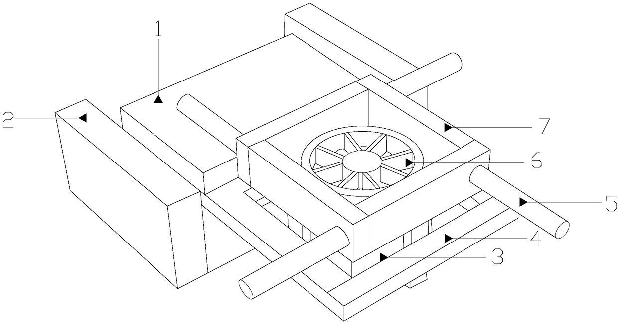
[0022] Such as Figure 1-Figure 5 As shown, the present invention provides a material diversion device for plastic molds, and its structure includes a quick and convenient diversion mechanism 1, a support plate 2, a diversion trough body 3, a clamping plate 4, a first water inlet pipe 5, a diversion plate body 6, and a guide Through the box body 7, the bracket plates 2 are provided with two, the bracket plates 2 are respectively welded to the two ends of the quick and convenient shunt mechanism 1 and fixedly connected by positioning pins, and the clamping plate 4 is fixed and welded to the quick and convenient shunt mechanism 1 The front end and the two are integrally formed. The bottom of the conduction box 7 is fixed on the upper end of the clamping plate 4 and is in contact with the quick and convenient shunt mechanism 1, and the upper end of the shunt tank body 3 is fixedly welded to the conduction box. The bottom of the body 7 is connected between the two, the first water ...


PUM


Abstract

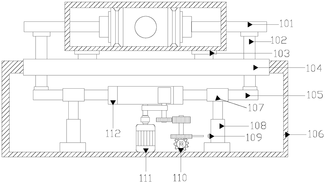
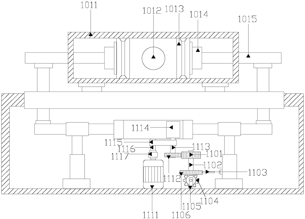
The invention discloses a material flow-dividing device for a plastic mould. The material flow-dividing device structurally comprises a fast and convenient flow-dividing mechanism, support plates, a flow-dividing trough, a clamping plate, first water inlet pipes, a flow-dividing disc and a conducting box. The support plates are welded to the two ends of the fast and convenient flow-dividing mechanism correspondingly and fixedly connected with the two ends of the fast and convenient flow-dividing mechanism through positioning pins. The clamping plate is fixedly welded to the front end of the fast and convenient flow-dividing mechanism, and the clamping plate and the front end of the fast and convenient flow-dividing mechanism are of an integrally formed structure. The bottom of the conducting box is fixedly arranged at the upper end of the clamping plate and makes contact with the fast and convenient flow-dividing mechanism. According to the material flow-dividing device for the plasticmould, a connecting rod is fixedly connected with a driving mechanism, the two sides of the driving mechanism are fixedly connected with first sliding rods, the first sliding rods are fixedly connected with second sliding rods through fixing rods, and the ends, inside a flow-dividing shell, of the second sliding rods are fixedly connected with pistons correspondingly, so that the problem of single structure of flow-dividing equipment is solved, the work efficiency is improved, the time is shortened, and the flow-dividing effect is better guaranteed.

Description

Technical field [0001] The invention is a material shunting device for plastic molds and belongs to the field of plastic molds. Background technique [0002] Plastic molds are tools that are matched with plastic molding machines in the plastic processing industry to give plastic products a complete configuration and precise dimensions. Due to the wide variety of plastics and processing methods, and the complicated and simple structures of plastic molding machines and plastic products, the types and structures of plastic molds are also diverse. According to different molding methods, different types of processing requirements can be divided. The types of plastic processing molds mainly include injection molding molds, extrusion molding molds, blister molding molds, high-expansion polystyrene molding molds, etc. Plastic injection (plastic) molds are mainly used in the production of thermoplastic parts. The corresponding processing equipment of the plastic injection mold is the pla...

Claims


Application Information

Patent Timeline
Patent Type & Authority Applications(China)
IPC IPC(8): B29C45/27
CPCB29C45/2703
Inventor 付维贤
Owner 李澎
Learn More