
Wiper and control system thereof, and control method thereof

A wiper and blade technology, applied in the fields of rail vehicles, automobiles and ships, to achieve the effect of flexible control mode and good stability

Pending Publication Date: 2018-12-18
CRSC RAIL CAR CO LTD
View PDF9 Cites 0 Cited by
  • Summary
  • Abstract
  • Description
  • Claims
  • Application Information

AI Technical Summary

Problems solved by technology

[0007] At the same time, a control method of the wiper is also proposed, which is used to solve the problems existing in the stability and service life of the existing wiper

Method used


Image

  • Wiper and control system thereof, and control method thereof
  • Wiper and control system thereof, and control method thereof

Examples


Embodiment Construction

[0053] In order to make the purpose, technical solutions and advantages of the embodiments of the present invention more clear, the technical solutions in the embodiments of the present invention are clearly and completely described below in conjunction with the drawings in the embodiments of the present invention. Obviously, the described embodiments are Some, but not all, embodiments of the invention. Based on the embodiments of the present invention, all other embodiments obtained by persons of ordinary skill in the art without making creative efforts belong to the protection scope of the present invention. It should be noted that, in the case of no conflict, the embodiments of the present invention and the features in the embodiments can be combined with each other. For the convenience of description, if the words "up", "down", "left" and "right" appear in the following, it only means that the directions of up, down, left and right are consistent with the drawings themselv...


PUM


Abstract

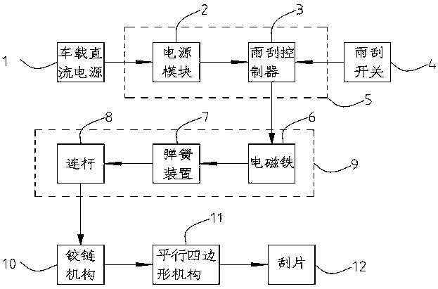
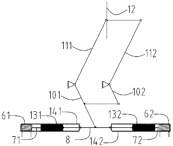
The invention discloses a wiper and a control system thereof, and a control method thereof. The wiper comprises a driving mechanism, a hinge mechanism connected with the driving mechanism, and a parallelogram mechanism connected with the hinge structure. The parallelogram mechanism is used for driving the blade of the wiper to oscillate. The driving mechanism comprises a housing with a sliding groove, a magnetic slider installed in the sliding groove and slidable reciprocally along the sliding groove, an electromagnet fixed on the housing, and a connecting rod. The other end of the magnetic slider is connected with one end of the connecting rod, the length direction of the connecting rod is consistent with the sliding direction of the magnetic slider, and the hinge mechanism is connected with the part of the connecting rod protruding from the sliding groove. The wiper of the invention remarkably improves the stability and service life of the wiper.

Description

technical field [0001] The invention relates to a wiper, a control system and a control method thereof, which belong to the field of wiper equipment for vehicles and are mainly used for rail vehicles, automobiles and ships. Background technique [0002] As we all know, the wiper includes a motor, a reducer, a four-bar linkage, a wiper arm spindle, a wiper blade, and the like. When the driver presses the switch of the wiper, the motor starts, and the speed of the motor drives the swing arm through the deceleration and torque increase of the worm gear. , and finally the rotating shaft drives the scraper to sweep the windshield. [0003] In recent years, with the support and investment of national policies, domestic rail vehicles have shown a blowout development trend. Rain gear is no exception. At present, the wipers of rail vehicles generally use motors as the power source to drive the scrapers to wipe the glass. The wipers have three different frequencies of high frequenc...

Claims


Application Information

Patent Timeline
IPC IPC(8): B60S1/08B60S1/16
CPCB60S1/08B60S1/16
Inventor 李敏尉法兵周柏舟
Owner CRSC RAIL CAR CO LTD
Learn More