

Equipment for collecting wastes in farmland ditch
A technology for collecting equipment and ditches, applied in the field of waste collection equipment in farmland ditches, can solve problems such as hindering the water-passing capacity of ditches, inconvenient cleaning of trash racks, and affecting farmland irrigation and drainage in irrigation areas.
- Summary
- Abstract
- Description
- Claims
- Application Information
AI Technical Summary
Problems solved by technology
Method used
Image

Examples
Embodiment 1
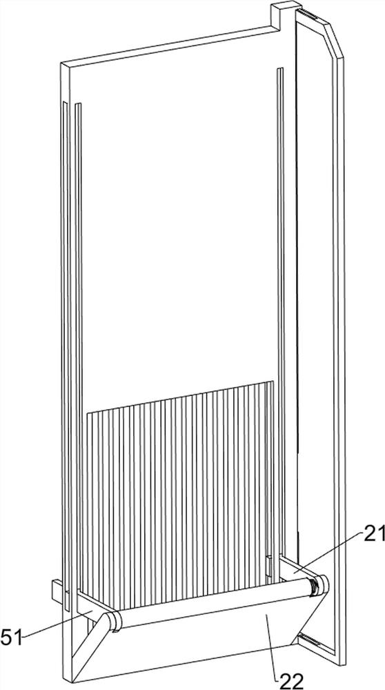
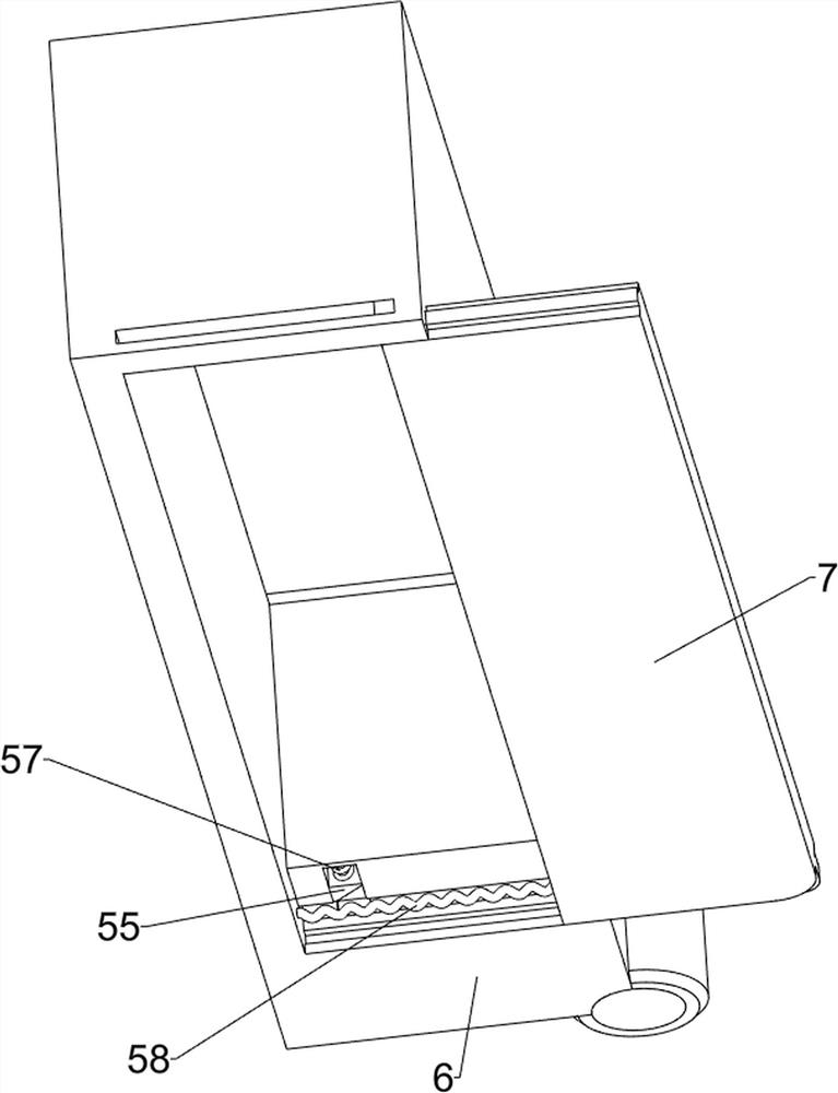
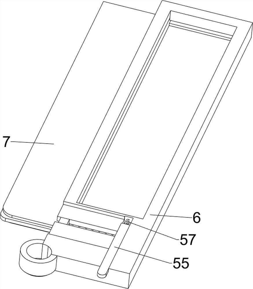
[0034] Such as figure 1 As shown, a waste collection device in farmland ditches includes a casing 1, a power mechanism 2, a cleaning mechanism 3, a sliding mechanism 4, a collection mechanism 5, a collection frame 6 and a baffle 7, and the right side of the inner wall at the front of the casing 1 is set There is a power mechanism 2, the lower part of the shell 1 is provided with a screen, the right side of the shell 1 is provided with a cleaning mechanism 3, the right side of the shell 1 is provided with a sliding mechanism 4, the cleaning mechanism 3 is provided with a collection mechanism 5, and the collection mechanism 5 is provided with a collection mechanism 5. Frame 6, a baffle plate 7 is slidingly provided at the bottom of the collecting frame 6 .
[0035] When it is necessary to clean up the floating garbage in the ditch of the farmland, the staff will place the device on the ditch. After a period of time, since the lower part of the shell 1 is provided with a screen, ...
Embodiment 2
[0037] Such as figure 1 , figure 2 , image 3 , Figure 4 , Figure 5 , Figure 6 , Figure 7 , Figure 8 , Figure 9 , Figure 10 , Figure 11 and Figure 12As shown, on the basis of Embodiment 1, the power mechanism 2 includes a motor 21, a rotating wheel 22, a belt 23, a fixed block 24 and a partition 25, and the right side of the inner wall at the front of the casing 1 is provided with a motor 21, and the motor 21 A rotating wheel 22 is arranged on the output shaft of the casing 1, and the same rotating wheel 22 is arranged on the inner wall on the right side of the lower part of the housing 1 through a pole. A belt 23 is connected between the two rotating wheels 22, and a belt 23 is arranged on the right side of the lower part of the belt. The fixed block 24 is provided with a partition 25 in the middle of the housing 1 .
[0038] The cleaning mechanism 3 includes a first slider 31, a scraper 32, a first torsion spring 33, a first fixed rod 34 and a first spri...
Embodiment 3
[0043] Such as figure 1 , Figure 13 and Figure 14 As shown, on the basis of Embodiment 2, an interception assembly 8 is also included. The interception assembly 8 includes a rotating plate 81, a slide bar 82, a second fixed bar 83 and a seventh spring 84. The left side of the front part of the partition plate 25 The rotary type is provided with a rotating plate 81, the sliding type on the left side of the front part of the dividing plate 25 is provided with a slide bar 82, and the front side of the sliding bar 82 is provided with a second fixed rod 83, and the second fixed rod 83 cooperates with the sliding type of the rotating plate 81 to slide A seventh spring 84 is connected between the top of the rod 82 and the left side of the top of the partition 25 .
PUM
 Abstract
Description
Claims
Application Information