Tunnel-strode support large-span stand column device

A large-span, column technology, used in excavation, construction, infrastructure engineering, etc., can solve the problems of small spacing and high density, and achieve the effect of increasing the spacing of column piles and reducing the number of column piles

Pending Publication Date: 2018-12-18
中船勘察设计研究院有限公司
View PDF4 Cites 0 Cited by
  • Summary
  • Abstract
  • Description
  • Claims
  • Application Information

AI Technical Summary

Problems solved by technology

Although the foundation pit project is a temporary structure, the enclosure structure often becomes an insurmountable obstacle on the tunnel to

Method used


Image

  • Tunnel-strode support large-span stand column device
  • Tunnel-strode support large-span stand column device
  • Tunnel-strode support large-span stand column device

Examples


Embodiment 1

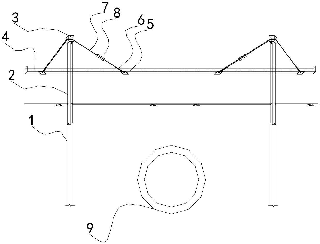
[0019] figure 1 It is a cross-sectional layout diagram of a medium-span tunnel supporting a large-span column device in Embodiment 1.

[0020] Such as figure 1 As shown, in this embodiment, the large-span column device for cross-tunnel support is arranged above the underpass tunnel 9 to realize the function of avoiding the underground tunnel 9 to be built below the bottom of the foundation pit.

[0021] The device for supporting large-span columns across the tunnel, including: two column pouring piles 1, two column lattice columns 2, two lattice column caps 3, concrete support 4, two steel strands 7, and four support anchor plates 5 and two strand tighteners 8.

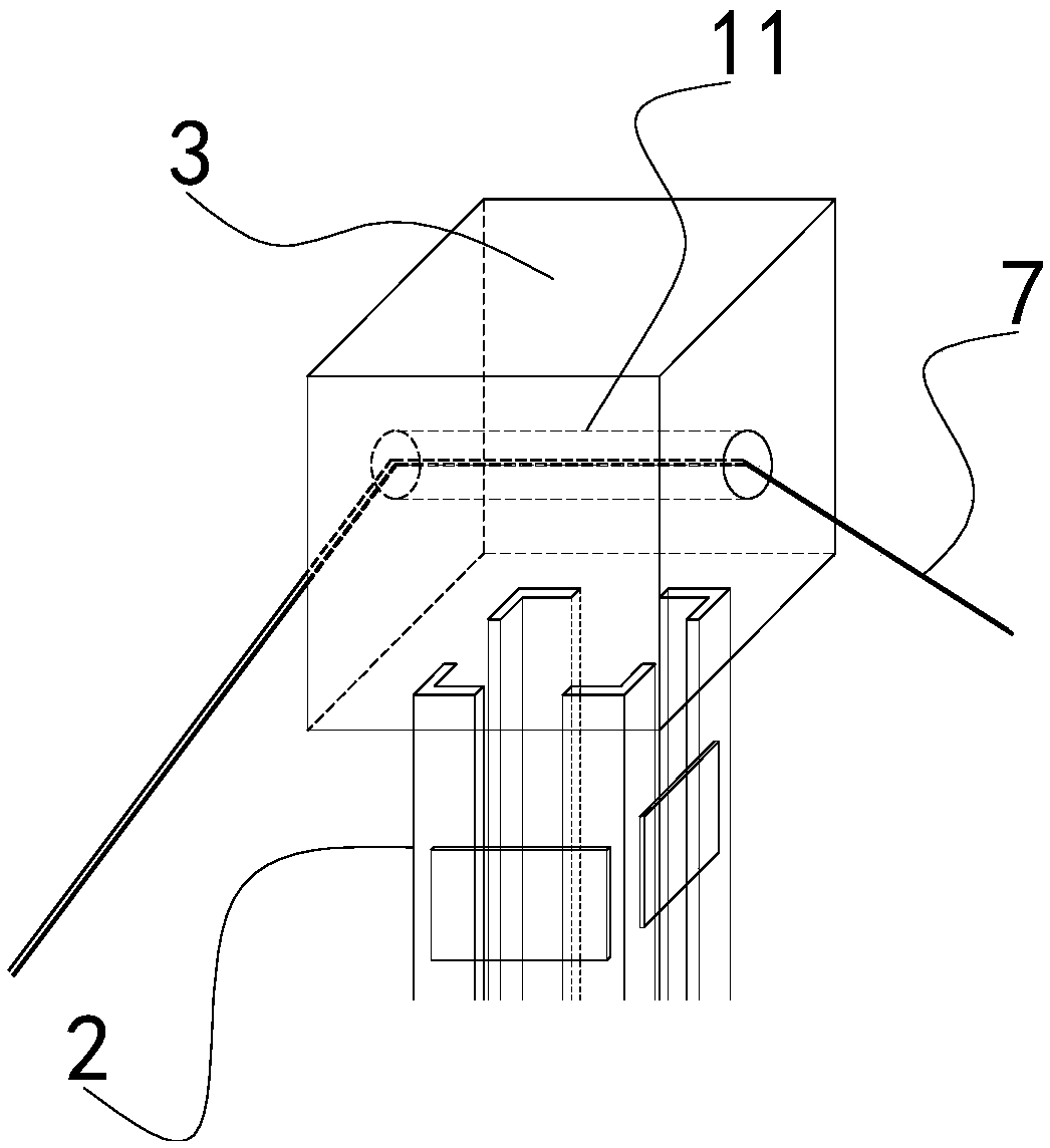
[0022] The column lattice column 1 corresponds to the column cast-in-place pile 2 one by one; the lower part of the column lattice column 2 and the steel cage on the upper part of the column cast-in-place pile 1 are welded and fixed, and they are lowered into place together when the column pile is constructed. The ...

Embodiment 2

[0031] In this embodiment, the large-span column device supported across the tunnel, except that the lattice column cap structure is different from that of Embodiment 1, the structures and working principles of other components are the same as those of Embodiment 1, and will not be described again.

[0032] Figure 4 It is a top half-sectional view of the connection position between the lattice column cap and the steel strand in the second embodiment.

[0033] Such as Figure 4 As shown, in this embodiment, three rollers 13 are also arranged in the hole 11 for the twisted wire of the lattice column cap 3 to pass through. Have groove on the roller shaft 13, and can rotate. The steel strand 7 is embedded in the groove; and is arranged parallel to the concrete support.


PUM


Abstract

The invention provides a tunnel-strode support large-span stand column device. The device comprises multiple stand column cast-in-place pile, multiple stand column latticed columns, multiple latticedcolumn caps, a concrete support, multiple stranded wires and multiple support anchor plates; the lower parts of the stand column latticed columns are fixedly connected with the upper parts of the stand column cast-in-place piles; the latticed column caps are fixed at the tops of the stand column latticed columns; the stranded wires penetrate through the latticed column caps, and two ends are positioned on two sides of the stand column latticed columns; the concrete support is horizontally arranged; the support anchor plates are arranged under the concrete support; and the two ends of the stranded wires penetrate through the concrete support, and are fixedly connected with the support anchor plates. The device has the following advantages: gaps of stand column pipes are increased to avoid from an underground tunnel to be constructed under a foundation pit bottom; the top elevations of the stand column latticed columns are increased; and the support above the tunnel to be constructed issuspended through the steel strands and the anchor plates to achieve the purpose of not constructing stand column piles in the area of the tunnel to be constructed, and the difficulty of difficult arrangement of the stand column piles after excavation of the deep foundation pit above the tunnel to be constructed is solved.

Description

technical field [0001] The invention relates to a device for supporting a large-span column across a tunnel, belonging to the technical field of underground engineering foundation pit support. Background technique [0002] With the development of the city, the land use is becoming increasingly tight, and more and more urban public facility tunnels pass under the buildings under construction. Considering the requirements of sustainable development, the structure under construction needs to reserve space for the planned construction of urban expressways, subway tunnels and other underground structures, so as to prevent the structure under construction from becoming an obstacle and affecting the construction of public facilities. Although the foundation pit project is a temporary structure, the enclosure structure often becomes an insurmountable obstacle on the tunnel to be built due to the existence of a large number of underground structures such as row piles and column piles...

Claims


Application Information

Patent Timeline
IPC IPC(8): E02D17/04
CPCE02D17/04
Inventor 杜策颜立明刘云忠魏仁杰吕志慧
Owner 中船勘察设计研究院有限公司
Why Eureka
Try Eureka