Pump structure and compressor

A pump body, gas pressure technology, applied in the field of compressors, can solve the problem of slow valve opening and closing, and achieve the effect of optimizing the exhaust volume

Pending Publication Date: 2018-12-18
ZHUHAI LANDA COMPRESSOR +1
View PDF6 Cites 0 Cited by
  • Summary
  • Abstract
  • Description
  • Claims
  • Application Information

AI Technical Summary

Problems solved by technology

[0004] In order to solve the defect of slow valve switch speed in the prior art, the present invention proposes a pump body structure and a compressor

Method used


Image

  • Pump structure and compressor
  • Pump structure and compressor
  • Pump structure and compressor

Examples


Embodiment Construction

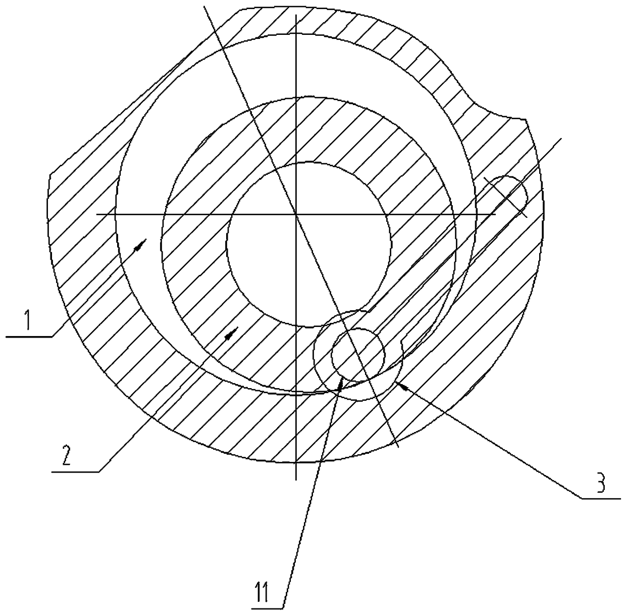
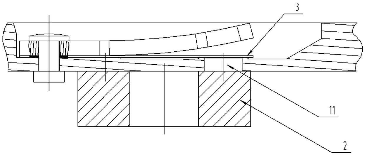
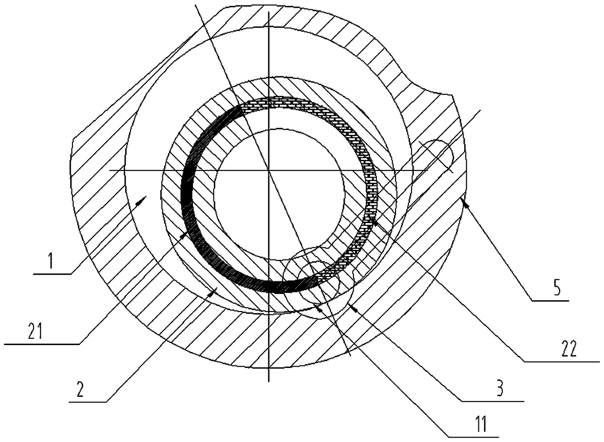
[0025] Such as Figures 3 to 5 As shown, the pump body structure proposed by the present invention includes: a working chamber 1, a roller 2 and a valve plate 3, the working chamber 1 is a cylindrical cavity, the end face of the working chamber 1 is provided with an exhaust hole 11, and the valve plate 3 is installed Outside the working chamber 1 , it is used to control the on-off state of the exhaust hole 11 . The area covering the exhaust hole 11 on the valve plate 3 is provided with a mounting hole, and a magnetic piece 31 is fixed in the mounting hole. The roller 2 is located in the working chamber 1. The shape of the roller 2 is circular. The outer circular surface of the roller 2 rolls along the wall of the working chamber 1. The end surface of the roller 2 near the exhaust hole 11 is provided with a magnetic strip. Group, roller 2 is provided with installation groove near the end face of exhaust hole 11, and magnetic stripe group is fixed in the installation groove, and...


PUM


Abstract

The invention discloses a pump structure and a compressor. The pump structure comprises a working chamber with an exhaust hole, a roller rolling in the working chamber, and a valve plate arranged on the outer part of the working chamber. A magnetic sheet is arranged on the area, covering the exhaust hole, on the valve plate; and a magnetic stripe group is arranged on the end surface, close to theexhaust hole, on the roller, and comprises a first magnetic stripe with the polarity same as the magnetic sheet and/or a second magnetic stripe with the polarity opposite to the magnetic sheet. When the first magnetic stripe rotates to be repelled to the magnetic sheet through the exhaust hole, the valve plate opens the exhaust hole; and when the second magnetic stripe rotates to be attracted withthe magnetic sheet through the exhaust hole, the valve plate closes the exhaust hole. According to the pump structure and the compressor provided by the invention, the opening-closing speed of the valve plate can be improved, the compression amount and the gas displacement are optimized, and the refrigerating capacity of the compressor is improved.

Description

technical field [0001] The invention relates to the technical field of compressors, in particular to a pump body structure and a compressor. Background technique [0002] Such as figure 1 , 2 As shown, in the operation of the existing rotary compressor, the exhaust hole 11 is exhausted through the opening and closing of the valve plate 3, and the opening and closing of the valve plate 3 is realized according to the pressure difference inside and outside the working chamber 1. The method of differential control valve 3 switch has the following defects: 1. The opening or closing speed of valve 3 is uncontrollable. When the pressure difference between the inside and outside of working chamber 1 is small, the closing speed of valve 3 is too slow, which will lead to the backflow of high-pressure gas outside the chamber. In cavity 1, it affects the displacement of the compressor, thereby reducing the cooling capacity of the compressor; 2. The opening or closing angle of the valv...

Claims


Application Information

Patent Timeline
Patent Type & Authority Applications(China)
IPC IPC(8): F04C29/12
CPCF04C29/124
Inventor 陈桂辉陈强
Owner ZHUHAI LANDA COMPRESSOR
Why Eureka
Try Eureka