Front passenger seat air bag apparatus

a front passenger seat and air bag technology, which is applied in the direction of pedestrian/occupant safety arrangements, vehicular safety arrangments, vehicle components, etc., can solve the problem of difficult escape of gas supplied into the air bag, and achieve the effect of smooth pulling and even smoother pulling

Inactive Publication Date: 2010-03-04
TOYOTA JIDOSHA KK
View PDF15 Cites 27 Cited by
  • Summary
  • Abstract
  • Description
  • Claims
  • Application Information

AI Technical Summary

Benefits of technology

[0008]This invention provides a front passenger seat air bag apparatus that is able to make the reaction force of an air bag when restraining a front seat passenger appropriate, regardless of whether the front seat passenger is wearing a seatbelt.
[0011]On the other hand, when a passenger seated in the front passenger seat is wearing a seatbelt and that passenger is restrained by the air bag, the second strap pulls on the edge portion of the vent hole as well as on the first strap, such that the vent hole that was closed (or in the process of being closed) by the operation of the first strap is opened again. As a result, it becomes easier for the gas inside the air bag to escape through the vent hole, so when a passenger seated in the front passenger seat is wearing a seatbelt, the reaction force against that passenger can be reduced, thus enabling that passenger to be appropriately restrained.
[0014]With the front passenger seat air bag apparatus according to this structure, the rear portion of the second strap extends in the vehicle width direction along the rear face of the base cloth that faces the passenger at a height position where the upper body of the passenger wearing a seatbelt will strike the air bag. Therefore, when the passenger is restrained by the air bag, the inertia force of the passenger is directly input to the second strap. As a result, the second strap pulls forcefully on the edge portion of the vent hole and the first strap, thereby more quickly opening the vent hole that had been closed, or in the process of being closed, by the operation of the first strap.
[0016]With the front passenger seat air bag apparatus according to this structure, the vent hole is provided in a side face of the base cloth of the air bag in the vehicle width direction when the air bag is in a deployed state. Further, a guide portion that guides the second strap is provided on the inside surface of the side face in a position that is farther toward the rear of the vehicle than the vent hole. Therefore, even if the rear face of the base cloth that faces the passenger is pushed forward in the longitudinal direction of the vehicle from the inertia force of the passenger, the portion of the second strap that is positioned along the side face of the air bag will be smoothly pulled toward the rear of the vehicle when the passenger wearing a seatbelt is restrained by the air bag. As a result, the edge portion of the vent hole and the first strap will be pulled toward the rear of the vehicle, such that the vent hole which had been closed, or in the process of being closed, by the operation of the first strap opens again. In this away, with the front passenger seat air bag apparatus having this structure, the operation of the second strap when the passenger wearing a seatbelt is restrained by the air bag is able to be even smoother.

Problems solved by technology

As a result, it becomes difficult for the gas supplied into the air bag to escape.

Method used


Image

  • Front passenger seat air bag apparatus
  • Front passenger seat air bag apparatus
  • Front passenger seat air bag apparatus

Examples


Embodiment Construction

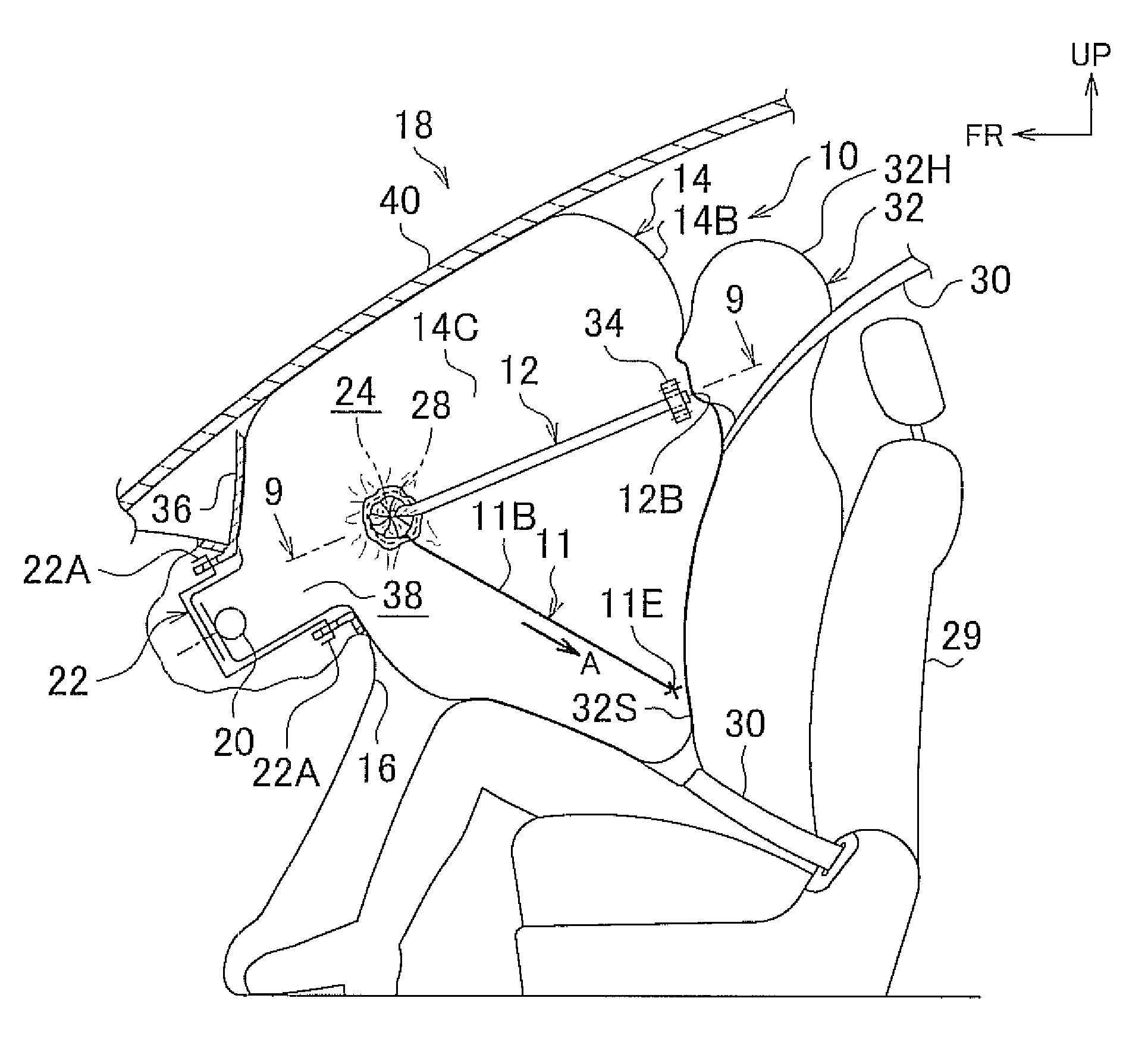
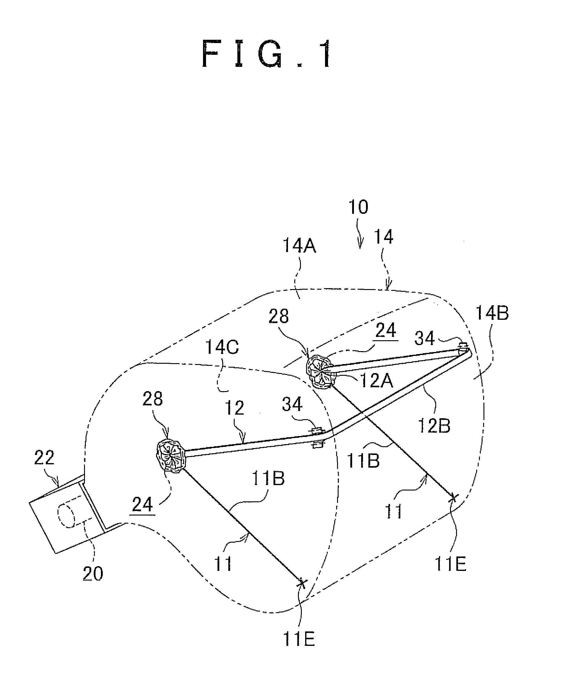
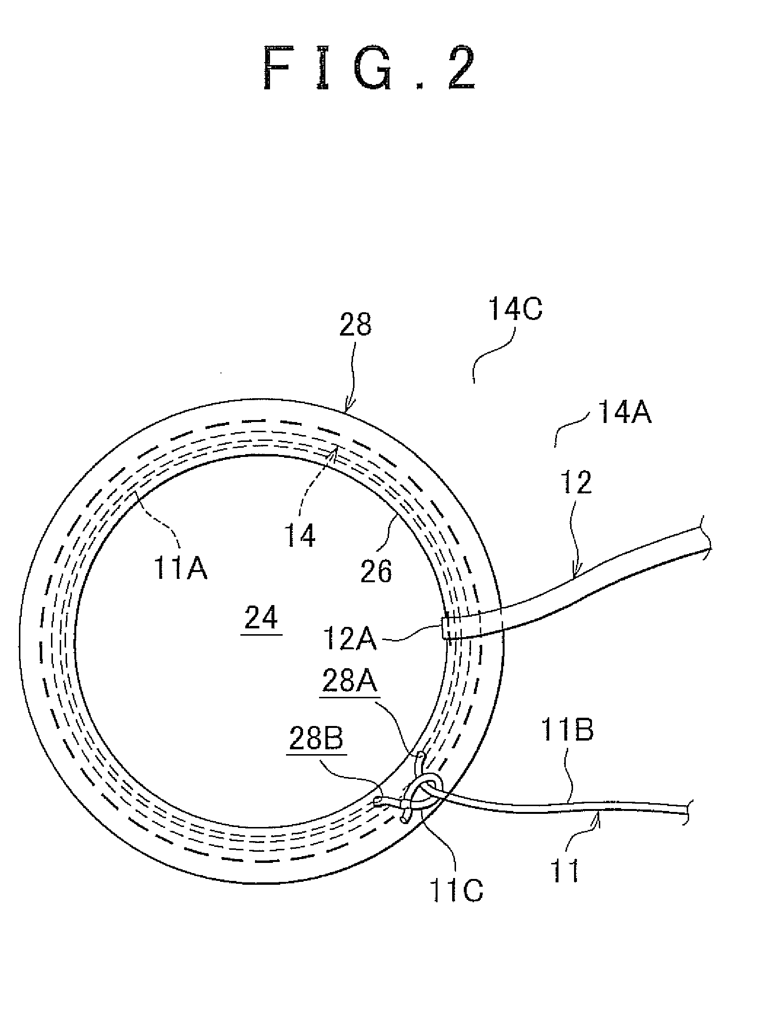
[0028]Example embodiments of the present invention will be described in greater detail below with reference to the accompanying drawings. In FIG. 1, a front passenger seat air bag apparatus 10 according to a first example embodiment includes an air bag 14 having vent holes 24, first straps 11, and a second strap 12.

[0029]The air bag 14 is normally housed folded inside an instrument panel 16. During a frontal collision of a vehicle 18, the air bag 14 is supplied with gas from an inflator 20, for example, so that it inflates and deploys toward a passenger 32 seated in a front passenger seat 29, as shown in FIG. 6. The air bag 14 and the inflator 20 are normally housed in a module case 22 which is arranged in the instrument panel 16. A plurality of pawl portions 22A are formed on the module case 22. These pawl portions 22A are engaged with the instrument panel 16. An open portion of the module case 22, which is the opening through which the air bag 14 inflates and deploys, is provided ...


PUM


Abstract

A passenger seat air bag apparatus includes an air bag which is housed folded inside an instrument panel, and inflates toward a passenger who is seated in a front passenger seat with a supply of gas during a frontal collision, and which has a vent hole that can be opened and closed; a first strap which is connected to both an area around the vent hole and a rear lower portion of a base cloth of the air bag in the longitudinal direction of the vehicle, and which closes the vent hole as the air bag inflates; and a second strap which is connected to an edge portion of the vent hole, and pulls on the edge portion of the vent hole and on the first strap around the vent hole so as to open the vent hole when the passenger who is wearing a seatbelt is restrained by the air bag.

Description

INCORPORATION BY REFERENCE[0001]The disclosure of Japanese Patent Application No. 2008-223587 filed on Sep. 1, 2008 including the specification, drawings and abstract is incorporated herein by reference in its entirety.BACKGROUND OF THE INVENTION[0002]1. Field of the Invention[0003]The invention relates to a front passenger seat air bag apparatus.[0004]2. Description of the Related Art[0005]U.S. Pat. No. 7,347,450 describes a front passenger seat air bag apparatus with a variable vent hole, in which a vent hole that is open when an air bag begins to inflate is closed by a strap as the air bag inflates. With this front passenger seat air bag apparatus, the strap is connected to the vent hole and a lower portion of the air bag that is toward the rear of the vehicle when the air bag is inflated.[0006]When a vehicle that is equipped with a front passenger seat air bag apparatus is involved in a frontal collision, the passenger seated in the front passenger seat is restrained by an air b...

Claims


Application Information

Patent Timeline
Patent Type & Authority Applications(United States)
IPC IPC(8): B60R21/16
CPCB60R21/205B60R2021/23388B60R21/239B60R21/2338
Inventor FUKAWATASE, OSAMUKURODA, TOMOTAKAAKASHIO, MUNEO
Owner TOYOTA JIDOSHA KK
Why Eureka
Try Eureka