Collection assembly

a technology for collecting containers and containers, which is applied in the field of collecting container assembly, can solve the problems of affecting the intended use of the container, affecting the shelf life of plastic tubes containing liquid additives, and affecting the shelf life of plastic tubes

Inactive Publication Date: 2011-06-14
BECTON DICKINSON & CO
View PDF72 Cites 30 Cited by
  • Summary
  • Abstract
  • Description
  • Claims
  • Application Information

AI Technical Summary

Benefits of technology

[0012]A further embodiment of the subject invention provides an inner tube that is sufficiently smaller than the outer tube to provide a small annular gap between the inner and outer tubes. The small annular gap between the inner and outer tubes permits air to escape easily as the inner tube is being telescoped into the outer tube. The outer surface of the inner tube includes a bead extending partly around the outer tube at a location near the open top. The bead may be formed unitarily with the inner tube or may be applied to the inner tube by adhesive or the like. The outside diameter defined by the bead is substantially equal to the inside diameter defined by the outer tube. The bead does not define a complete annulus. Rather, at least one gap is defined in the bead. Air can escape readily from the space between the inner and outer tubes as the cross-sectionally small inner tube is being telescoped into the outer tube. A complete annular bead around the inner tube would prevent further escape of air as the inner tube approaches its final nested position within the outer tube. However, the small gap in the annular bead permits the escape of air as the inner tube approaches its final nested position within the outer tube. Thus, air in the small annular gap between the inner and outer tubes is at ambient pressure and will not define a high pressure area that is likely to migrate through the plastic material of the inner tube and into the space defined by the inner tube. After assembly, the inner tube is spun relative to the outer tube. Thus, a friction weld is created between the inner and outer tubes for securely sealing the space between the tubes.
[0013]Another embodiment of the subject invention provides an inner tube with an outside diameter that is sufficiently smaller than the inside diameter of the outer tube to define an annular gap therebetween. Thus, as with the previous embodiment, the inner tube can be telescoped readily into the outer tube without generating a region of compressed air between the inner and outer tubes. The closure of this assembly includes a short cylindrical wall dimensioned to telescope into the annular space between the inner and outer tubes at a location substantially adjacent the open top of the inner tube. Thus, the short cylindrical wall of the closure seals the space between the inner and outer tubes. The closure also includes an inner section disposed and dimensioned to seal with the inner circumferential surface of the inner tube. An alternate to this embodiment provides a closure with a radially aligned step to cover the open top of the annular space between the inner and outer tubes without entering the annular space between the inner and outer tubes. The closure of this embodiment also includes an inner portion to seal with the inner circumferential surface of the inner tube.
[0014]A further embodiment of the subject invention includes an inner tube with an outside diameter that is sufficiently smaller than the inside diameter of the outer tube to define an annular gap therebetween. Thus, as with the previous embodiment, the inner tube can be telescoped readily into the outer tube without generating a region of compressed air between the inner and outer tubes. Portions of the inner tube at locations near the open top include a circumferentially extending weakened region. The weakened region may be created by an annular groove extending around the outer circumferential surface of the inner tube. A similar annular groove may be formed around the inner circumferential surface at a location substantially aligned with the annular groove on the outer circumferential surface. The closure of this assembly includes a tapered region with a small diameter leading end that defines a diameter approximately equal to the inside diameter of the inner tube. The closure then widens to an outside diameter substantially equal to the inside diameter of the outer tube. The tapered configuration enables the closure to function as a wedge that causes the inner tube to deform outwardly as the closure is being urged into the open tops of the inner and outer tubes. Thus, the portions of the inner tube adjacent the open top will flare outwardly and will be urged tightly against the inner circumferential surface of the outer tube as the closure is being urged into the open tops of the nested tubes.
[0016]Another embodiment of the subject invention includes an inner tube with an outside diameter that is sufficiently less than the inside diameter of the outer tube to define an annular gap between the inner and outer tubes. Thus, as with the previous embodiments, the inner tube can be telescoped into a fully nested condition within the outer tube without creating compressed air in the annular space between the inner and outer tubes. The assembly of this embodiment further includes a retaining ring. The retaining ring is dimensioned to nest with and seal the space between the inner and outer tubes. The sealing can be facilitated by chamfering the outer top surface of the inner tube and / or forming the retaining ring with a taper.

Problems solved by technology

Therefore, it is difficult to maintain the shelf-life of plastic tubes that contain a liquid additive.
It is also appreciated that deterioration of the volume and concentration of the liquid additive may interfere with the intended use of the tube.
Furthermore, air trapped between the two closely fitting nestable containers can complicate or prevent complete nesting.
However, the grooves complicate the respective structures and the grooved containers still require close dimensional tolerances.
This approach, however, complicates and lengthens an otherwise efficient manufacturing cycle.

Method used


Image

  • Collection assembly
  • Collection assembly
  • Collection assembly

Examples


Embodiment Construction

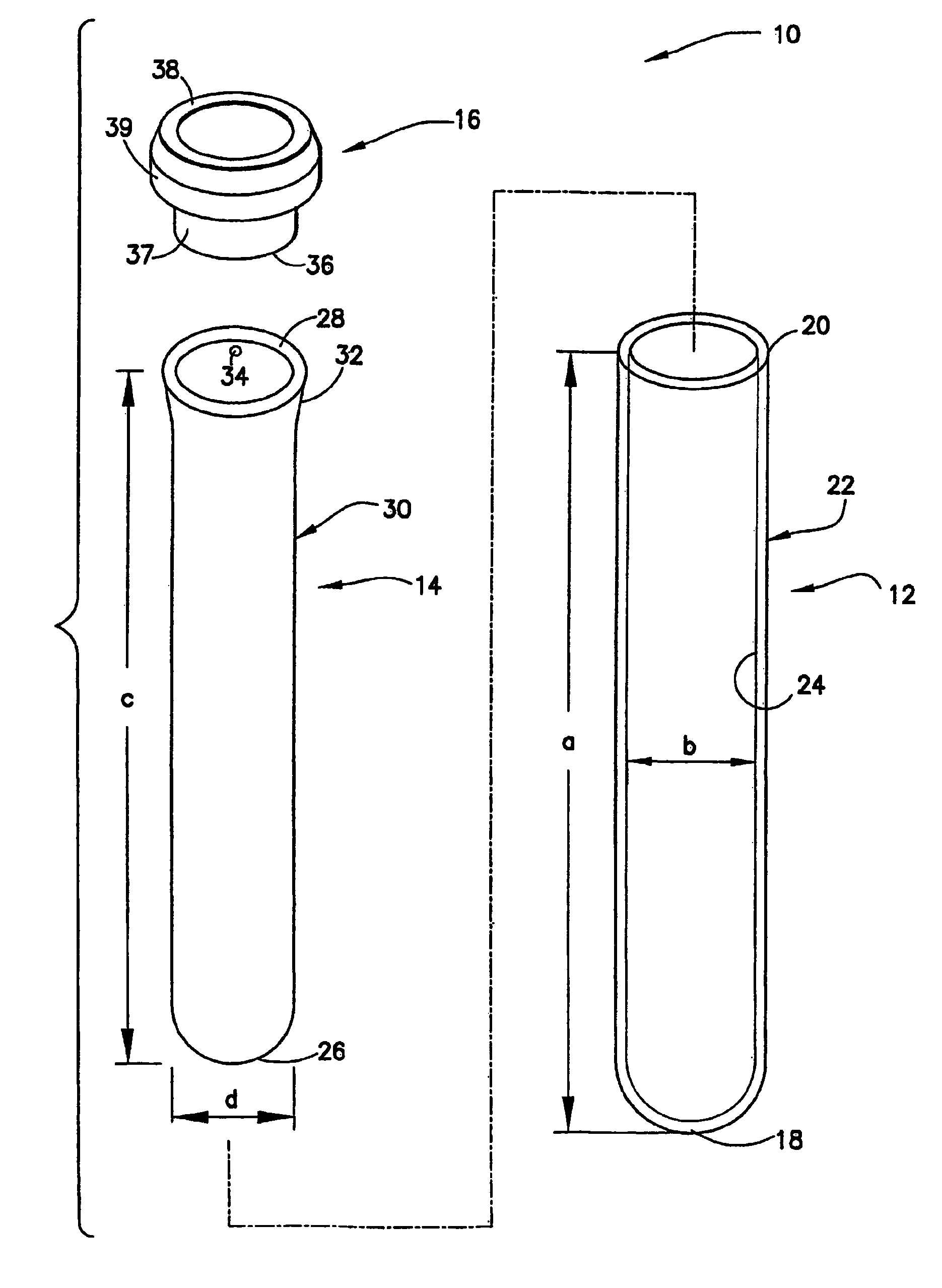
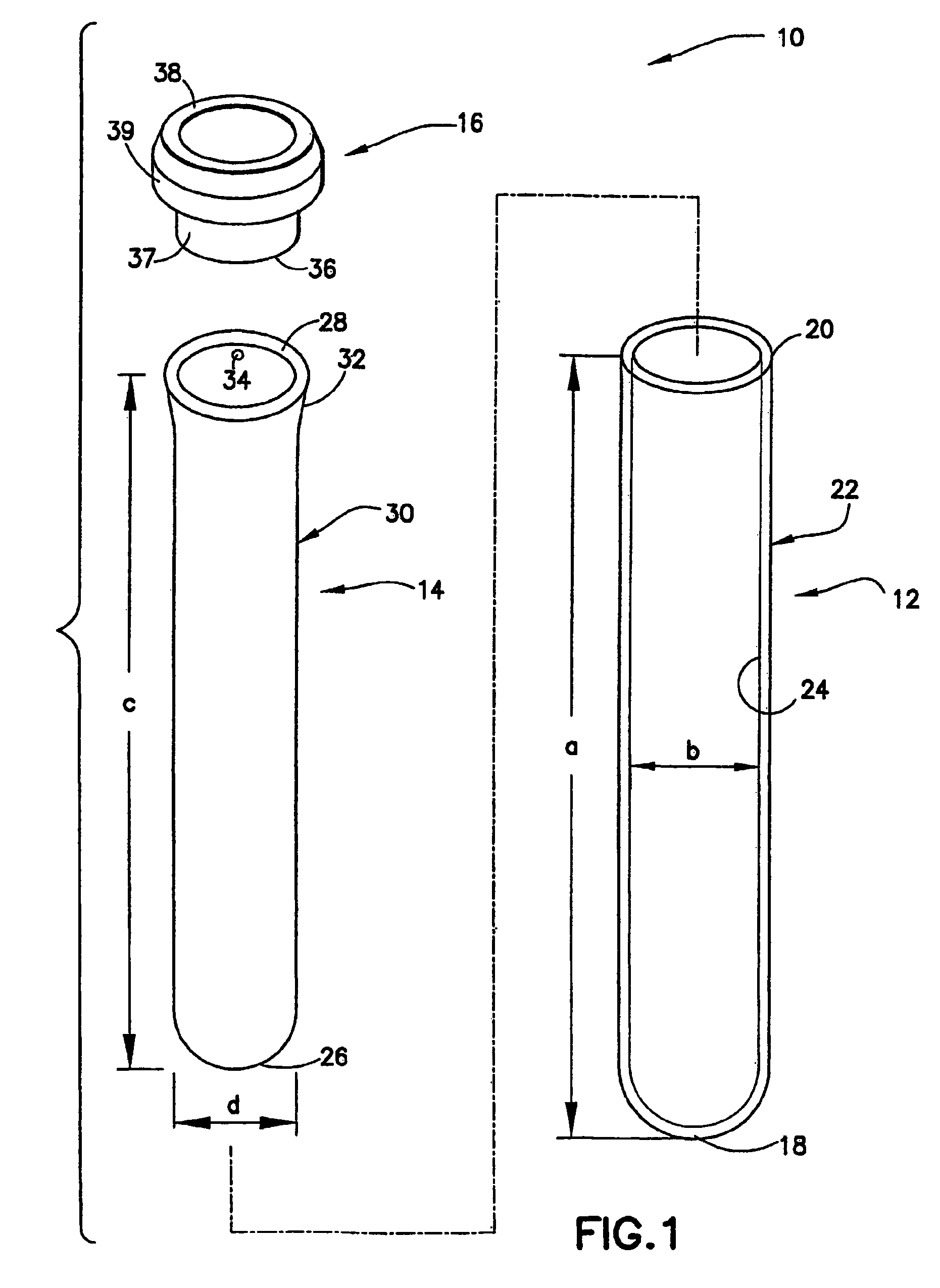
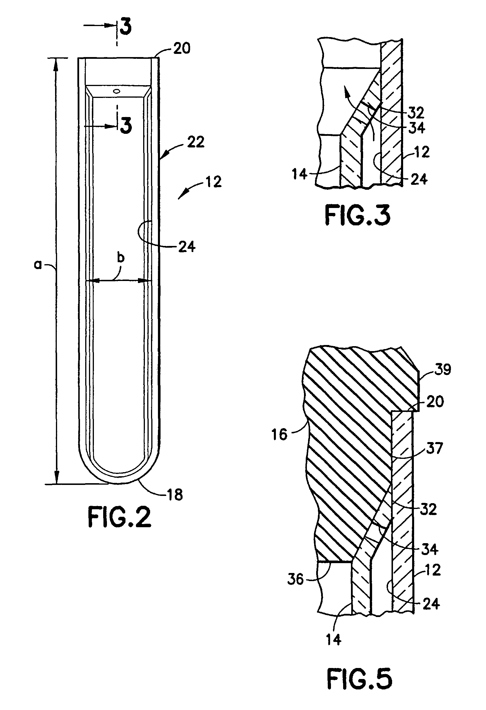
[0041]An assembly in accordance with a first embodiment of the subject invention is identified generally by the numeral 10 in FIGS. 1-5. Assembly includes an outer tube 12, an inner tube 14 and a closure 16.

[0042]Outer tube 12 is unitarily formed from PET and includes a spherically generated closed bottom wall 18, an open top 20 and a cylindrical wall 22 substantially extending therebetween. Outer tube 12 defines a length “a” from the interior of the bottom wall 18 to the open top 20. Side wall 22 of outer tube 12 includes a cylindrically generated inner surface 24 with an inside diameter “b”. However, side wall 22 may taper slightly from open top 20 to closed bottom wall 18 to facilitate molding.

[0043]Inner tube 14 is formed unitarily from polypropylene and includes a spherically generated closed bottom wall 26, an open top 28 and a substantially cylindrical side wall 30 extending therebetween. Inner tube 14 defines an external length “c” that is less than internal length “a” of ou...


PUM


Abstract

A tube assembly includes an inner tube telescoped into an outer tube. The inner tube is dimensioned to define a substantially annular space between the inner and outer tubes. Portions of the inner tube near its open top are configured to permit venting as the inner tube is inserted into the open top. However, the vent is closed during insertion of a closure into the tube assembly or prior to inserting a closure into the tube assembly.

Description

BACKGROUND OF THE INVENTION[0001]1. Field of the Invention[0002]The invention relates to a collection container assembly that includes a plurality of nested containers formed from different respective materials and provides an effective barrier against water and gas permeability and for extending the shelf-life of assembly.[0003]2. Description of the Related Art[0004]Plastic tubes have an inherent permeability to water transport due to the physical properties of the plastic materials used to manufacture the tubes. Therefore, it is difficult to maintain the shelf-life of plastic tubes that contain a liquid additive. It is also appreciated that deterioration of the volume and concentration of the liquid additive may interfere with the intended use of the tube.[0005]In addition, plastic tubes that are used for blood collection require certain performance standards to be acceptable for use in medical applications. Such performance standards include the ability to maintain greater than a...

Claims


Application Information

Patent Timeline
Patent Type & Authority Patents(United States)
IPC IPC(8): B01L3/00B01L3/14B01L9/06
CPCB01L3/5082B01L9/06B01L2300/10B01L2200/141B01L2300/042B01L2200/0684
Inventor CRAWFORD, JAMIESON W. M.HUTTON, NORMAN J.FERGUSON, MARGIE M.ISKRA, MICHAEL
Owner BECTON DICKINSON & CO
Why Eureka
Try Eureka