Plating apparatus and method

a technology of plating apparatus and plating film, which is applied in the field of apparatus and method for plating, can solve the problems of lowering the properties of the plated film, affecting the quality of the plating, and affecting and achieves the effect of easy removal of bubbles that can adversely affect the quality of the plating

Inactive Publication Date: 2008-07-22
EBARA CORP
View PDF28 Cites 33 Cited by
  • Summary
  • Abstract
  • Description
  • Claims
  • Application Information

AI Technical Summary

Benefits of technology

[0012]The present invention has been made in view of the above drawbacks in the related art. It is therefore a first object of the present invention to provide a plating apparatus and method which enables a plating liquid entering into fine trenches and plugs for wiring and into openings of a resist formed in a substrate, without adding a surfactant to the plating liquid, and without suffering from plating defects and incomplete plating.
[0013]It is a second object of the present invention to provide a plating apparatus which employs the dipping method in which air bubbles can escape relatively easily, and is capable of automatically forming a plated metal film suitable for protruding connecting electrodes such as bumps, and which does not occupy a large space.

Problems solved by technology

Such air bubbles can cause plating defects or incomplete plating.
Further, the addition of a surfactant to the plating liquid can cause an abnormal plating deposition and increase the amount of an organic substance taken in the plated film, leading to lowering of the properties of the plated film.
According to the dipping method of electrolytic plating, bubbles that can adversely affect the quality of the plating are easily removed and the footprint is small.
Since such a substrate holder is immersed in the plating liquid with the substrate when plating the surface of the substrate, it is difficult to automate the entire plating process from loading of the substrate to unloading of the substrate after plating.
Further, the plating apparatus occupies a considerably large space.

Method used


Image

  • Plating apparatus and method
  • Plating apparatus and method
  • Plating apparatus and method

Examples


first embodiment

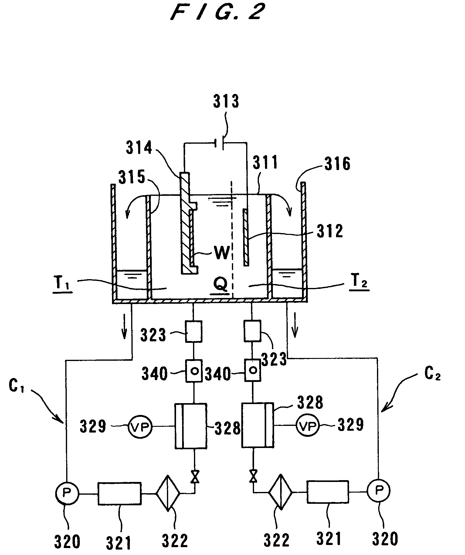
[0075]Preferred embodiments of a plating apparatus according to the present invention will be described with reference to FIGS. 1 through 28. FIG. 1 shows the construction of a plating apparatus according to the present invention. As shown in FIG. 1, the plating apparatus includes a cation exchange membrane 318 as a diaphragm which is disposed between a cathode (substrate W) and an anode 312 connected to a plating power source 313. The cation exchange membrane (diaphragm) 318 partitions the space in the plating tank 311 into two regions, T1 including the substrate W and T2 including the anode 312. The plating apparatus of this embodiment is a copper-plating apparatus designed to form a plated copper film on the surface (processing surface to be plated) of the substrate W. The anode 312 is a soluble anode and a plating liquid Q is a copper sulfate solution. The substrate W, which is detachably held by the substrate holder 314 with a watertight seal being made over the backside of the...

third embodiment

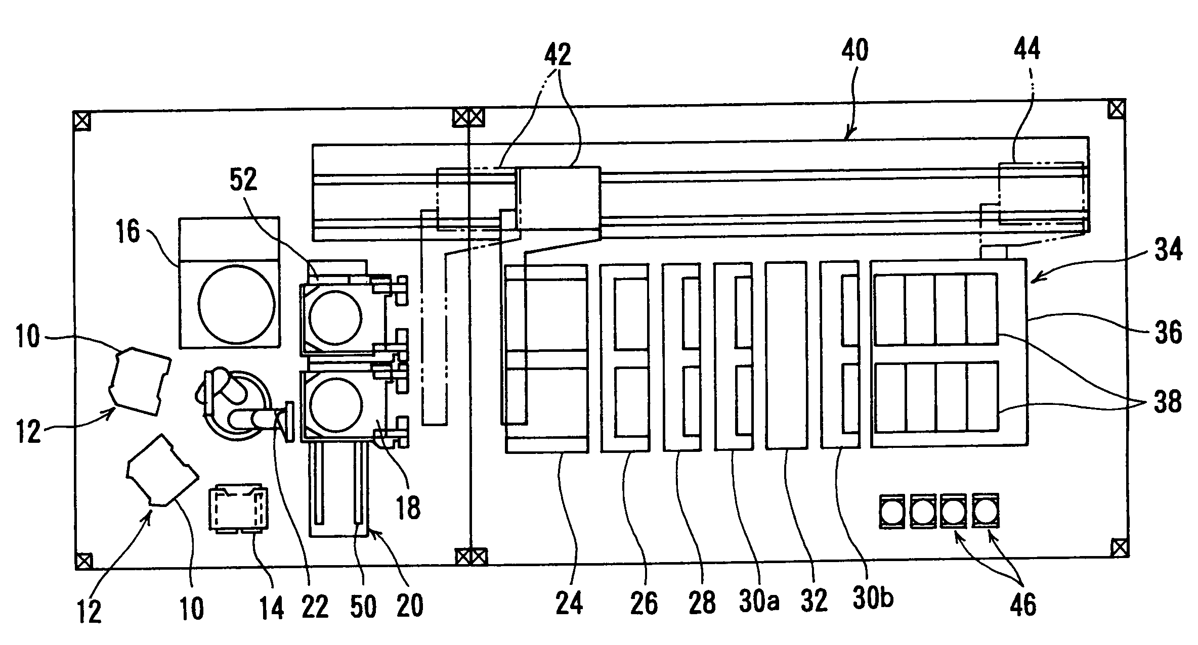
[0089]FIG. 3A shows the overall construction of a plating apparatus according to the present invention. As shown in FIG. 3A, the plating apparatus is provided with two cassette tables 12 for placing thereon cassettes 10 that house substrates W, such as semiconductor wafers; an aligner 14 for aligning the orientation flat or notch, etc. of the substrate W in a prescribed direction; and a spin dryer 16 for spin drying the substrate at a high rotation speed after the plating process, all arranged along the same circle. A substrate loading / unloading unit 20 for placing the substrate holders 18 thereon, which detachably hold the substrates, is provided along a tangent line to the circle. A substrate transferring device 22, such as a transferring robot, is disposed in the center of these units for transferring substrates W therebetween.

[0090]As shown in FIG. 3B, it is also possible to provide, around the substrate transferring device 22, a resist peeling unit 600 for peeling the resist 50...

fourth embodiment

[0160]FIGS. 22A and 23 show a plating apparatus according to the present invention. This apparatus is provided with plating tanks for performing different types of plating processes and adapted to various processes freely.

[0161]FIG. 22A shows a plating section provided with plating tanks for performing various types of plating processes. The plating section includes the stocker 24; a temporary storing platform 240; the pre-wetting tank 26; the pre-soaking tank 28; the first cleaning tank 30a; a nickel plating tank 244 having an overflow tank 36a and a plurality of nickel plating units 242 disposed in the overflow tank 36a for performing nickel plating on the surface of a substrate; the second cleaning tank 30b; the copper plating tank 34 having the overflow tank 36 and a plurality of the copper plating units 38 disposed in the overflow tank 36 for performing copper plating on the surface of a substrate; the third cleaning tank 30c; the blowing tank 32; the fourth cleaning tank 30d; ...


PUM

PropertyMeasurementUnit
heightaaaaaaaaaa
diameteraaaaaaaaaa
concentrationaaaaaaaaaa

Abstract

An apparatus forms a plated film in fine trenches and plugs for interconnects and in the openings of a resist formed in the surface of a substrate such as a semiconductor wafer, and forms bumps (protruding electrodes) on the surface of a semiconductor wafer. The apparatus includes a substrate holder capable of opening and closing for holding a substrate such that the front surface of the substrate is exposed while the backside and the edge thereof are hermetically sealed. A plating tank accommodates a plating liquid in which an anode is immersed. A diaphragm is provided in the plating tank and disposed between the anode and the substrate held by the substrate holder. Plating liquid circulating systems circulate the plating liquid to respective regions of the plating tank, separated by the diaphragm. A deaerating unit is disposed in at least one of the plating liquid circulating systems.

Description

[0001]This is a Divisional Application of U.S. patent application Ser. No. 09 / 809,295, filed Mar. 16, 2001 now abandoned.BACKGROUND OF THE INVENTION[0002]1. Field of the Invention[0003]The present invention relates to an apparatus and method for plating the processing surface, to be plated, of a substrate, and more particularly to a plating apparatus and method suited for forming a plated film in fine trenches and plugs for interconnects, and in the openings of a resist formed in the surface of a substrate such as a semiconductor wafer, and for forming bumps (protruding electrodes) on the surface of a semiconductor wafer for electrically connecting semiconductor chips and the substrate.[0004]2. Description of the Related Art[0005]FIG. 30 shows the general construction of a conventional plating apparatus for plating copper or the like on a semiconductor substrate. As shown in FIG. 30, the conventional substrate plating apparatus is provided with a plating tank 411 that holds a platin...

Claims


Application Information

Patent Timeline
Patent Type & Authority Patents(United States)
IPC IPC(8): C25D17/00B23H7/26C25D7/12C25D21/04C25D21/10C25D21/12
CPCC25D17/02C25D21/04C25D21/10C25D21/12C25D17/004C25D17/001C25D17/002C25D17/06C25D7/123C25D17/00
Inventor YOSHIOKA, JUNICHIROSAITO, NOBUTOSHIMUKAIYAMA, YOSHITAKATOKUOKA, TSUYOSHI
Owner EBARA CORP
Why Eureka
Try Eureka