Device and method for coiled material centering and diameter measuring

A caliper and coil technology, applied in measuring devices, optical devices, instruments, etc., can solve the problems of unreachable caliper, occupying a large space, inconvenient installation, etc., achieving high precision, simple and reliable device, Easy to install effect

Inactive Publication Date: 2009-09-23
上海东大自动化工程有限公司
View PDF0 Cites 23 Cited by
  • Summary
  • Abstract
  • Description
  • Claims
  • Application Information

AI Technical Summary

Problems solved by technology

In this device, the bracket that drives the sensor to move, including the support arm, is controlled by a hydraulic system including a set of hydraulic cylinders and hydraulic valves, which occupies a large space and is inconvenient to install
Moreover, this method can only play a centering role and cannot achieve the purpose of measuring diameter.

Method used


Image

  • Device and method for coiled material centering and diameter measuring
  • Device and method for coiled material centering and diameter measuring
  • Device and method for coiled material centering and diameter measuring

Examples


Embodiment 1

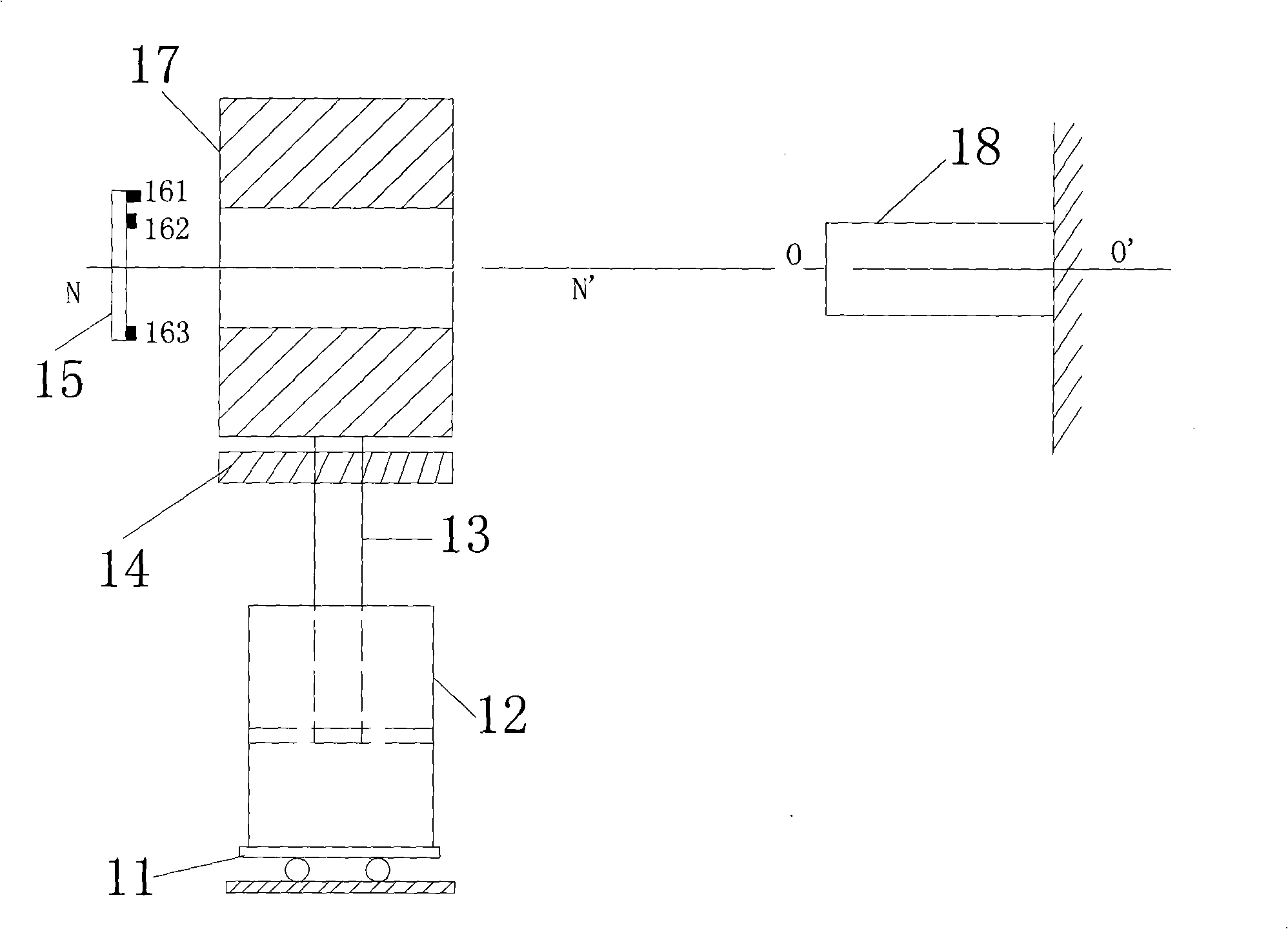
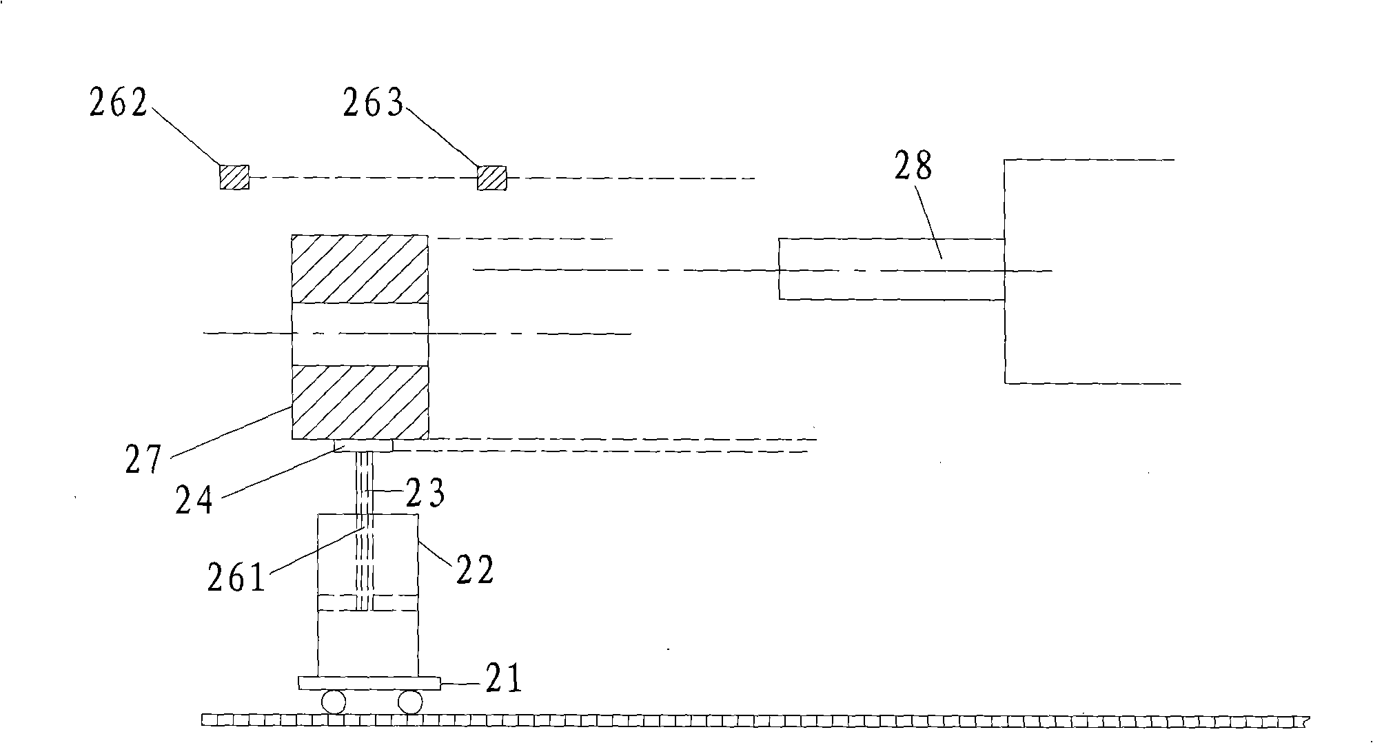
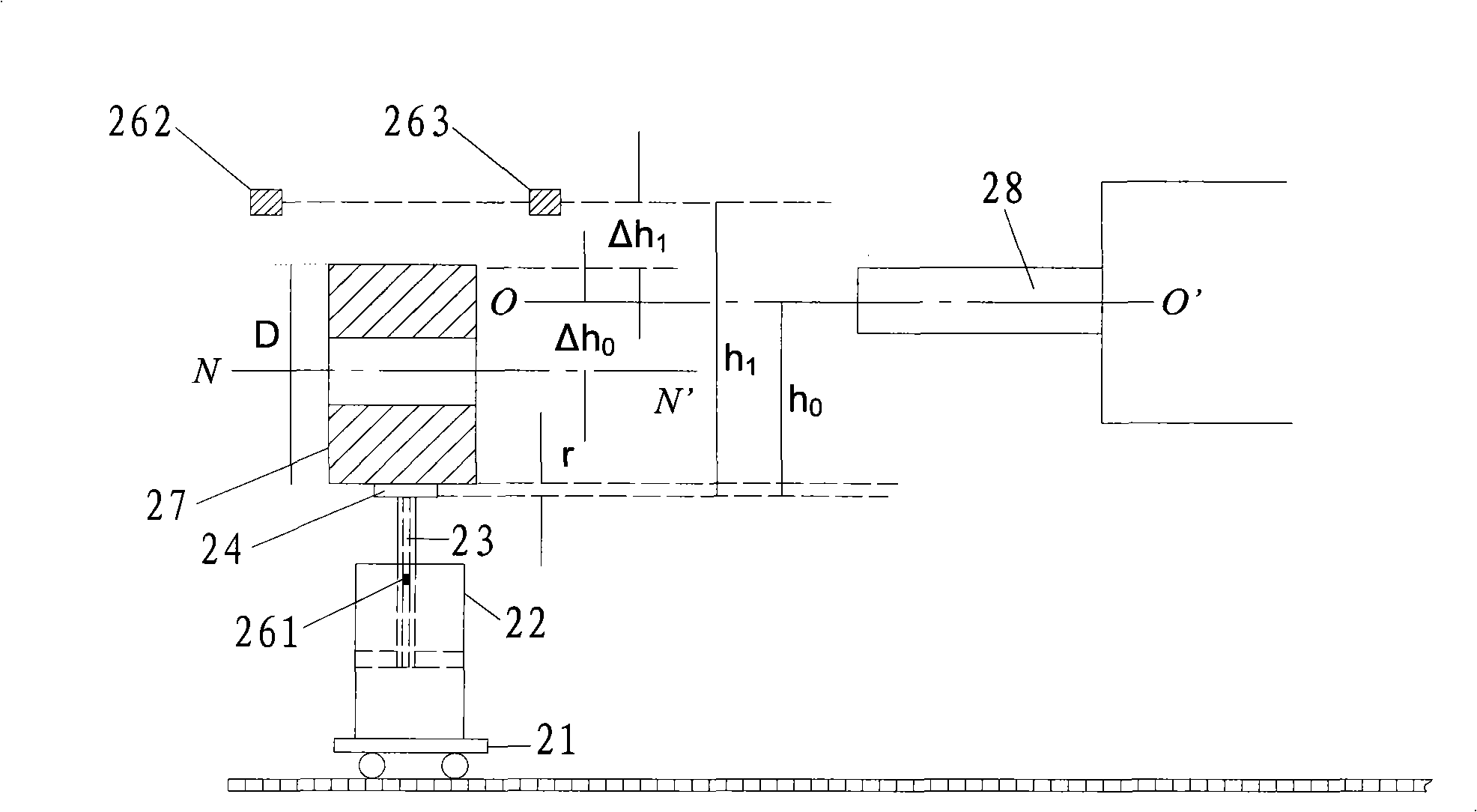
[0021] A coil centering diameter measuring device, comprising a trolley 21, a hydraulic cylinder 22, a push rod 23, a bracket 24, a displacement sensor A 261, a photoelectric sensor B 262, a photoelectric sensor C 263, an analog / digital converter 29 and a PLC 30, The specific structure is: a hydraulic cylinder 22 is fixed on the trolley 21 that can move left and right, a push rod 23 is fixed on the piston of the hydraulic cylinder 22, a bracket 24 is fixed on the top of the push rod 23, and a displacement sensor A 261 is fixed inside the push rod 23 , the position signal generated by the displacement sensor A 261 has a linear relationship with the moving distance of the ejector rod 23, the photoelectric sensor B 262 and the photoelectric sensor C 263 are fixed directly above the bracket 24, and the photoelectric sensor B 262 and the photoelectric sensor C 263 are on the same horizontal line Above, the displacement sensor A 261, the photoelectric sensor B 262 and the photoelectr...

Embodiment 2

[0027] A coil centering diameter measuring device, comprising a trolley 21, a hydraulic cylinder 22, a push rod 23, a bracket 24, a displacement sensor A 261, a grating B 362, a grating C 363, an analog / digital converter 29 and a single-chip microcomputer 40, specifically The structure is: a hydraulic cylinder 22 is fixed on the trolley 21 that can move left and right; The position signal generated by the displacement sensor A 261 has a linear relationship with the moving distance of the ejector rod 23. The grating B 362 and the grating C 363 are fixed directly above the bracket 24, and the grating B 362 and the grating C 363 are on the same horizontal line. The displacement sensor A 261, grating second 362 and grating third 363 are all connected with single-chip microcomputer 40 through analog / digital converter 29.

[0028]When using this embodiment for centering and diameter measurement, the steel coil 27 is fixed on the bracket 24, and the piston of the hydraulic cylinder 2...


PUM


Abstract

The invention relates to the filed of coiled profile supplied to a machine and diameter measurement, in particular to a device and a method for coiled material centering and diameter measuring. The device comprises a dolly, a hydraulic cylinder, a mandril and a bracket. The hydraulic cylinder is fixed on the dolly which can move leftwards and rightwards; the mandril is fixed on the piston of the hydraulic cylinder; and the bracket is fixed on the top of the mandril. The device is characterized by also comprising a displacement sensor A, a photoelectric sensor B, a photoelectric sensor C, an analog / digital converter and a PLC; the displacement sensor A is fixed inside the mandril; linear relation exists between position signals generated by the displacement sensor A and the movement distance of the mandrill; the photoelectric sensor B and the photoelectric sensor C are fixed above the bracket and positioned on the same horizontal line; and the displacement sensor A, the photoelectric sensor B and the photoelectric sensor C are all connected with the PLC through the analog / digital converter. The invention has the advantages of simpleness, reliability, convenient installation and high control and measurement accuracy and is beneficial to quantitative statistic.

Description

technical field [0001] The invention relates to the field of supplying coiled profiles and diameter measurement to a machine, in particular to a coil centering diameter measuring device and method. Background technique [0002] At present, in the coil centering control of the uncoiler of the strip steel production line in the metallurgical industry, the commonly used figure 1 The centering device shown is composed of trolley 11, hydraulic cylinder 12, ejector rod 13, bracket 14, movable support 15 and sensors 161-163. Its structure is: trolley 11 can move left and right, and trolley 11 is fixed with hydraulic pressure cylinder 12, the piston of the hydraulic cylinder 12 is fixed with a push rod 13, the piston can drive the push rod 13 to move up and down, the top of the push rod 13 is fixed with a bracket 14, the sensors 161-163 are all fixed on the movable support 15, the sensor 161 The distance between and 163 equals the diameter of steel coil 17 middle part through holes...

Claims


Application Information

Patent Timeline
Patent Type & Authority Applications(China)
IPC IPC(8): B21C51/00B21C47/24G01B11/10G01B11/00
Inventor 王朝利王燕飞
Owner 上海东大自动化工程有限公司
Why Eureka
Try Eureka