Low vibration diaphragm coupling used in high speed and high power working conditions

A high-power, vibrating diaphragm technology, used in couplings, elastic couplings, mechanical equipment, etc., can solve problems affecting the stability and safety of the rotor system, the large amplitude of the diaphragm coupling, and the occurrence of the coupling. Severe vibration and other problems, to achieve the effect of improving safety and stability, increasing effective damping, and reducing vibration amplitude

Active Publication Date: 2018-12-18
XI AN JIAOTONG UNIV
View PDF6 Cites 2 Cited by
  • Summary
  • Abstract
  • Description
  • Claims
  • Application Information

AI Technical Summary

Problems solved by technology

Due to the high rotational speed of the aero-engine, the rotational speed in the test often exceeds the critical rotational speed of the thin-walled sleeve, resulting in severe vibration of the coupling during the critical process, seriously affecting the st

Method used


Image

  • Low vibration diaphragm coupling used in high speed and high power working conditions

Examples


Embodiment Construction

[0024] The present invention is described in further detail below in conjunction with accompanying drawing:

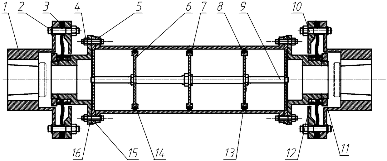
[0025] Such as figure 1 As shown, the present invention provides a low-vibration diaphragm coupling applied to high-speed and high-power working conditions, including a coupling half 1, a metal diaphragm 3, a splined sleeve 16, a laminate 10, and a positioning metal Diaphragm sleeve 12 , thin-wall sleeve 5 , O-ring damper or O-wire damper 14 , first to third discs 6 - 8 , mandrel 9 and support plate 15 .

[0026] figure 1 For low-vibration, high-speed, high-power diaphragm couplings used in large-scale rotating rotors, one end of the two half-couplings 1 is connected to the rotor, and the other end is connected to the motor. A small misalignment is allowed during the installation of the two shafts, and it can transmit large torque.

[0027] The metal diaphragm 3 is installed on the splined sleeve 16. By positioning the metal diaphragm sleeve 12 in the axial directio...


PUM


Abstract

The invention relates to a low vibration diaphragm coupling used in high speed and high power working conditions. The low vibration diaphragm coupling includes semi-couplings, a thin-wall sleeve and so on. Supporting plates, sleeves with splines and the semi-couplings are symmetrically arranged on both ends of the thin-wall sleeve, and the supporting plates, the sleeves with splines and the semi-couplings are successively connected, wherein a core shaft is arranged on the central axis of the thin-wall sleeve, the two ends of the core shaft are correspondingly connected to the centers of the supporting plates on both ends of the thin-wall sleeve, a plurality of disks are installed on the core shaft at intervals, and dampers are arranged between the disks and the inner wall of the thin-wallsleeve; and the thin-wall sleeve, the supporting plates and the sleeves with splines are fastened by bolts, metal diaphragms are arranged on the other ends of the sleeves with splines in a sleeving mode in the circumferential direction, and the outer sides of the metal diaphragms are connected to the corresponding semi-couplings through laminates. The low vibration diaphragm coupling used in the high speed and high power working conditions has high application value for rotor connection design of rotating machinery such as a steam turbine, a turbine, a compressor and an aero-engine. The low vibration diaphragm coupling used in the high speed and high power working conditions has good functions of vibration suppression and vibration reduction, the critical vibration amplitude of the thin-wall sleeve in the diaphragm coupling can be significantly reduced, and the stability of the coupling is improved.

Description

technical field [0001] The invention belongs to the field of shaft coupling design, and in particular relates to a low-vibration diaphragm shaft coupling applied to high-speed and high-power working conditions. Background technique [0002] Before leaving the factory, the high and low pressure rotors of aero-engines need to test the dynamic performance of the rotors such as critical speed, unbalanced response and stability under high speed and high power conditions. During the experiment, the motor is used as the power source. A coupling is used to connect the aero-engine and the electric motor. However, since the coupling has a certain stiffness, connecting with the measured rotor will add additional stiffness to the rotor, which will affect the dynamic characteristics of the rotor system. In order to improve the accuracy of the test, the couplings used in the aero-engine test have the following requirements: 1. The dynamic and static performance of the rotor system itself...

Claims


Application Information

Patent Timeline
IPC IPC(8): F16D3/56
CPCF16D3/56
Inventor 裴世源洪军李超王文超郑文斌徐华
Owner XI AN JIAOTONG UNIV
Why Eureka
Try Eureka