[0019] All the features disclosed in this specification, or all disclosed methods or steps in the process, except for mutually exclusive features and/or steps, can be combined in any manner.
[0020] Any feature disclosed in this specification (including any appended claims, abstract and drawings), unless specifically stated, can be replaced by other equivalent or alternative features with similar purposes. That is, unless otherwise stated, each feature is just one example of a series of equivalent or similar features.
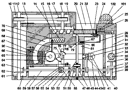
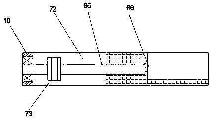
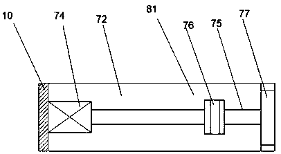
[0021] Such as Figure 1-3 As shown, a short rear seat type automatic rifle magazine loading device of the device of the present invention includes a loading box 10 and a magazine conveying device arranged in the loading box 10, and the loading box 10 is provided with There is a first rotating cavity 13, the loading box 10 is provided with a fifth rotating cavity 60 located on the lower side of the first rotating cavity 13, and the loading box 10 is provided with the first rotating cavity 13 The lower side of the bomb transport chamber 19, the loading box 10 is provided with a top pressure chamber 26 located on the left side of the bomb transport chamber 19, and the loading box 10 is provided with an upper side of the top pressure chamber 26 And the replenishment cavity 21 communicating with the top pressure cavity 26, the replenishment cavity 21 is open upward, the loading box 10 is provided with a third rotating cavity 43 located on the lower side of the top pressure cavity 26, so The loading box 10 is provided with a second rotating cavity 30 located on the right side of the third rotating cavity 43, and the loading box 10 is provided with a sixth rotating cavity 81 located on the left side of the third rotating cavity 43. , The back side of the sixth rotation cavity 81 is provided with a seventh rotation cavity 72 communicating with the sixth rotation cavity 81 and the third rotation cavity 43, and a motor 74 is fixed on the back wall of the seventh rotation cavity 72 , The front end of the motor 74 is dynamically connected with a thirteenth rotating shaft 75 extending forward into the sixth rotating cavity 81 and rotatably connected with the front wall of the sixth rotating cavity 81, and the thirteenth rotating shaft 75 is fixed A fifth pulley 76 is provided, the thirteenth shaft 75 is fixedly provided with a sector gear 77 located on the front side of the fifth pulley 76, and the rear wall of the seventh rotating chamber 72 is rotated with a front end extending to the first A twelfth rotating shaft 65 in the six rotating chamber 81 and rotatably connected to the front wall of the sixth rotating chamber 81, and a fourth gear 64 fixedly connected to the twelfth rotating shaft 65 is provided in the sixth rotating chamber 81 , The loading box 10 is provided with a squeezing cavity 69 located on the upper side of the sixth rotating cavity 81, and the magazine conveying device includes a front wall of the seventh rotating cavity 72 and the front end and the outside. A connected box slot 90, a magazine box 66 slidably arranged in the box slot 90, the magazine box 66 is provided with a magazine slot 67 for placing magazines and communicating with the press chamber 69, so The rear side of the magazine groove 67 is provided with a threaded cavity, the rear wall of the seventh rotating cavity 72 is rotated to provide a screw 86 that cooperates with the magazine groove 67, and the screw 86 is fixedly provided with the bullet On the seventh pulley 73 on the rear side of the box 66, the bottom wall of the compression chamber 69 is slidably provided with a compression block 70, and the right end of the compression block 70 is fixedly provided with a right end which is fixedly connected to the right wall of the compression chamber 69 The return spring 14 of the pressure spring block 70 is fixedly provided with a lower end fixedly connected to the outer side of the front end surface of the fourth gear 64, and the loading box 10 is provided with the lower side of the pressure chamber 26 and The top pressure cavity 26 and the first sliding cavity 20 communicated with the pull wire 31 are provided with a second connecting rod 52 whose upper end extends into the first sliding cavity 20 on the top wall of the sixth rotating cavity 81. The lower end of the second connecting rod 52 is slidably fitted with the bottom wall of the sixth rotation cavity 81, and the lower end of the second connecting rod 52 is fixedly provided with a lower end and a local sixth rotation. A second pressing spring 47 is fixedly connected to the bottom wall of the moving cavity 81, a first limiting block 78 is fixed on the second connecting rod 52, and the sixth rotating cavity 81 is provided with a rotatably connected to the second The third gear 51 of the connecting rod 52 is provided with a lighting device on the upper end surface of the loading box 10, and the lighting device includes a lamp holder 101 and a lighting lamp 102.
[0022] Beneficially or exemplarily, the bullet loading box 10 is provided with a fourth rotating cavity 59 located on the lower side of the sixth rotating cavity 81, and the left wall of the fourth rotating cavity 59 is rotated with a left end extending to The tenth rotating shaft 58 in the fifth rotating cavity 60 is provided with a ninth bevel gear 57 fixedly connected to the right end of the tenth rotating shaft 58 in the fourth rotating cavity 59, and the right wall of the fourth rotating cavity 59 An eighth rotating shaft 53 whose right end extends to the sixth rotating cavity 81 is provided for rotation. A seventh bevel gear 54 fixedly connected to the left end of the eighth rotating shaft 53 is provided in the fourth rotating cavity 59. The front and rear walls of the four rotating chamber 59 are provided with a ninth rotating shaft 55. The ninth rotating shaft 55 is fixedly provided with a sixth pulley 85 that cooperates with the fifth pulley 76. The ninth rotating shaft 55 is fixedly provided with a On the front side of the sixth pulley 85 and the eighth bevel gear 56 meshing with the ninth bevel gear 57 and the seventh bevel gear 54, the sixth rotation cavity 81 is provided with a fixed connection to the eighth rotation shaft 53 The second gear 50 at the right end.
[0023] Beneficially or exemplarily, wherein the left and right walls of the third rotating cavity 43 are provided with a seventh rotating shaft 42 whose left end extends into the sixth rotating cavity 81 and the right end extends into the second rotating cavity 30, The third rotation cavity 43 is provided with a fourth pulley 45 fixedly connected to the seventh rotation shaft 42, and the sixth rotation cavity 81 is provided with a first gear fixedly connected to the left end of the seventh rotation shaft 42 46. The left wall of the third rotating cavity 43 is provided with a third rotating shaft 33, the third rotating shaft 33 is fixedly provided with a third pulley 40 that cooperates with the fourth pulley 45, and the right end of the third rotating shaft 33 A first bevel gear 32 is fixedly provided, and the rear wall of the seventh rotation cavity 72 is rotated and provided with a sixth rotation shaft 41 whose front end extends into the third rotation cavity 43 and is rotatably connected with the front wall of the third rotation cavity 43 , The third rotation cavity 43 is provided with a sixth bevel gear 44 fixedly connected to the sixth rotation shaft 41 and meshed with the first bevel gear 32, and the seventh rotation cavity 72 is provided with a fixed connection to the The sixth rotating shaft 41 and the eighth pulley that cooperates with the seventh pulley 73, the left wall of the third rotating cavity 43 is provided with a second sliding cavity 80 communicating with the third rotating cavity 43, and A second limit block 79 is slidably provided in the second sliding cavity 80. The right end of the second limit block 79 is fixedly provided with a right end 87 connected to the right wall of the second sliding cavity 80. The second limit The rear end of the block 79 is fixedly provided with a first connecting rod 29 passing through the third rotating cavity 43 and extending into the first sliding cavity 20 at the other end.
[0024] Beneficially or illustratively, the second rotating cavity 30 is provided with a fifth bevel gear 38 fixedly connected to the right end of the seventh rotating shaft 42, and the bottom wall of the second rotating cavity 30 is rotated with a fifth bevel gear 38. A rotating shaft 39, a third bevel gear 36 is fixed on the upper end of the fifth rotating shaft 39, and a third bevel gear 36 is fixed on the fifth rotating shaft 39, which is located under the third bevel gear 36 and meshes with the fifth bevel gear 38 For the fourth bevel gear 37, the front and rear walls of the second rotating cavity 30 are provided with a fourth rotating shaft 35, the fourth rotating shaft 35 is fixedly provided with a wire wheel, and a cable wire 31 is wound on the wire wheel. A second bevel gear 34 which is located on the front side of the wire wheel and meshed with the third bevel gear 36 is fixed on the four rotating shaft 35, and a pressing block 24 is slidably provided in the pressing cavity 26. The right end of the block 24 is fixed with the right end fixedly connected to the first pressing spring 25 on the right wall of the pressing chamber 26, the upper end of the pull wire 31 is fixedly connected to the right end surface of the pressing block 24, and the pressing chamber 26 is placed There is a bullet 23 on the left side of the pressing block 24, and a sliding block 22 fixedly connected to the pressing block 24 is slidably provided in the first sliding cavity 20.
[0025] Beneficially or illustratively, the fifth rotating cavity 60 is provided with an eleventh bevel gear 63 fixedly connected to the left end of the tenth rotating shaft 58, and the upper and lower walls of the fifth rotating cavity 60 are rotated with upper ends. A first rotation shaft 12 extending into the first rotation cavity 13 and rotatably connected to the top wall of the first rotation cavity 13, and the fifth rotation cavity 60 is provided with a fixed connection to the first rotation shaft 12 and The tenth bevel gear 62 meshed with the eleventh bevel gear 63, the first rotation cavity 13 is provided with a first pulley 11 fixedly connected to the first rotation shaft 12, and the upper and lower walls of the first rotation cavity 13 The rotation is provided with a second rotating shaft 18 whose lower end extends into the local transport chamber 19, and a second pulley fixedly connected to the second rotating shaft 18 and matched with the first pulley 11 is provided in the first rotating cavity 13 17. A turntable 16 fixedly connected to the lower end of the second rotating shaft 18 is provided in the bomb transport cavity 19, and an elastic groove 15 is provided on the outer circular surface of the turntable 16.
[0026] Beneficially or illustratively, a lamp holder 101 is fixedly arranged on the upper end surface of the bullet loading box 10, the lamp holder 101 is connected to a power source, and the upper end of the lamp holder is fixedly installed with a lighting lamp 102, and the lighting device It can be used for lighting at night.
[0027] In the initial state, the right end of the sliding block 22 presses the first connecting rod 29 so that the second limiting block 79 is located at the rightmost end, and the third gear 51 is connected to the second gear 50 and the first Gear 46 is not engaged.
[0028] When starting to reload, the motor 74 is started, the thirteenth shaft 75 drives the fifth pulley 76, the fifth pulley 76 drives the sixth pulley 85, and the sixth pulley 85 drives the first pulley. The nine bevel gear 57 and the seventh bevel gear 54 rotate, the ninth bevel gear 57 drives the tenth rotation shaft 58 to rotate, the tenth rotation shaft 58 drives the eleventh bevel gear 63 to rotate, and the The eleven bevel gear 63 drives the tenth bevel gear 62 to rotate, the tenth bevel gear 62 drives the eleventh rotating shaft 61 to rotate, the eleventh rotating shaft 61 drives the first pulley 11 to rotate, and the The first pulley 11 drives the second pulley 17 to rotate, the second pulley 17 drives the second rotating shaft 18 to rotate, the second rotating shaft 18 drives the turntable 16 to rotate, and the turntable 16 drives the bullet 23 Transported to the compression chamber 69, while the thirteenth shaft 75 drives the sector gear 77 to rotate, the sector gear 77 drives the fourth gear 64 to rotate, and the fourth gear 64 drives the The third connecting rod 68 rotates, the third connecting rod 68 drives the elastic block 70 to press the bullet 23 into the magazine, and the elastic block 70 is reset and reset under the pull of the return spring 14 Circulate movement to achieve loading.
[0029] When the loading is completed, the top pressure block 24 moves to the left side of the top pressure cavity 26, the slider 22 presses the second connecting rod 52 downward, and the second limit block 79 pops up with the The first limiting block 78 cooperates to prohibit the second connecting rod 52 from rebounding, the third gear 51 meshes with the second gear 50 and the first gear 46, and the seventh bevel gear 54 drives the The eighth rotating shaft 53 rotates, the eighth rotating shaft 53 drives the second gear 50 to rotate, the second gear 50 drives the third gear 51 to rotate, and the third gear 51 drives the first gear 46 to rotate , The first gear 46 drives the fourth pulley 45 to rotate, the fourth pulley 45 drives the third pulley 40 to rotate, the third pulley 40 drives the third rotating shaft 33, the third rotating shaft 33 drives the first bevel gear 32 to rotate, the first bevel gear 32 drives the sixth bevel gear 44 to rotate, the sixth bevel gear 44 drives the sixth rotation shaft 41 to rotate, the sixth rotation shaft 41 Drive the eighth pulley to rotate, the eighth pulley drives the seventh pulley 73 to rotate, the seventh pulley 73 drives the screw 86 to rotate, and the screw 86 drives the magazine box 66 forward Movement to replace the next magazine, so as to realize the change of the magazine.
[0030] At the same time, the seventh rotation shaft 42 drives the fifth bevel gear 38 to rotate, the fifth bevel gear 38 drives the fourth bevel gear 37 to rotate, and the fourth bevel gear 37 drives the fifth rotation shaft 39 to rotate. , The fifth rotating shaft 39 drives the fourth bevel gear 37 to rotate, the fourth bevel gear 37 drives the third bevel gear 36 to rotate, and the third bevel gear 36 drives the second bevel gear 34 to rotate , The second bevel gear 34 drives the fourth shaft 35 to rotate, the fourth shaft 35 drives the wire wheel to rotate, the wire wheel drives the pull wire 31 to pull the pressing block 24 to reset, the The second limiting block 79 returns to the initial state, the second connecting rod 52 returns to the initial state, the third gear 51 is disengaged from the second gear 50 and the first gear 46, so that the device is reset. Bullets can be filled into the pressing cavity 26.
[0031] The beneficial effects of the present invention are:
[0032] When starting to reload, start the motor, the thirteenth shaft drives the fifth pulley, the fifth pulley drives the sixth pulley, and the sixth pulley drives the ninth bevel gear, the The seventh bevel gear rotates, the ninth bevel gear drives the tenth shaft to rotate, the tenth shaft drives the eleventh bevel gear to rotate, and the eleventh bevel gear drives the tenth bevel gear to rotate , The tenth bevel gear drives the eleventh shaft to rotate, the eleventh shaft drives the first pulley to rotate, the first pulley drives the second pulley to rotate, and the second pulley drives the The second rotating shaft rotates, the second rotating shaft drives the turntable to rotate, the turntable conveys the bullets into the squeeze cavity, and at the same time the thirteenth rotating shaft drives the sector gear to rotate, so The sector gear drives the fourth gear to rotate, the fourth gear drives the third connecting rod to rotate, and the third connecting rod drives the elastic block to press the bullet into the magazine. The elastic block is reset and cyclically moved under the pulling of the return spring, so as to realize the loading;
[0033] When the loading is completed, the top pressure block moves to the left side of the top pressure cavity, the sliding block presses the second connecting rod downward, and the second limit block pops up with the first limit block Matching to prohibit the second connecting rod from rebounding, the third gear meshes with the second gear and the first gear, the seventh bevel gear drives the eighth shaft to rotate, and the eighth shaft drives The second gear rotates, the second gear drives the third gear to rotate, the third gear drives the first gear to rotate, the first gear drives the fourth pulley to rotate, and the fourth gear rotates. A pulley drives the third pulley to rotate, the third pulley drives the third rotating shaft, the third rotating shaft drives the first bevel gear to rotate, and the first bevel gear drives the sixth bevel gear to rotate, The sixth bevel gear drives the sixth shaft to rotate, the sixth shaft drives the eighth pulley to rotate, the eighth pulley drives the seventh pulley to rotate, and the seventh pulley drives the screw rod Rotate, the screw rod drives the magazine box to move forward to change the next magazine, thereby realizing the change of the magazine;
[0034] At the same time, the seventh rotation shaft drives the fifth bevel gear to rotate, the fifth bevel gear drives the fourth bevel gear to rotate, the fourth bevel gear drives the fifth rotation shaft to rotate, and the fifth rotation shaft Drive the fourth bevel gear to rotate, the fourth bevel gear drives the third bevel gear to rotate, the third bevel gear drives the second bevel gear to rotate, and the second bevel gear drives the fourth bevel gear The rotating shaft rotates, the fourth rotating shaft drives the wire wheel to rotate, the wire wheel drives the pulling wire to pull the pressing block to reset, the second limit block returns to the initial state, and the second connecting rod returns In the initial state, the third gear is disengaged from the second gear and the first gear, so that the device can be reset and the bullet can be filled into the pressure cavity;
[0035] This device is simple in structure and easy to use. It can realize automatic loading of automatic rifle magazines. At the same time, the magazine can be automatically switched after loading is completed, which greatly accelerates the loading speed and replaces the traditional manual loading. It is on the battlefield where time is precious. It saves valuable time for soldiers and increases combat capability.
[0036] The above shows and describes the basic principles, main features and advantages of the present invention. Those skilled in the industry should understand that the present invention is not limited by the above-mentioned embodiments. The above-mentioned embodiments and the specification describe only the principles of the present invention. Without departing from the spirit and scope of the present invention, the present invention will have various aspects. Various changes and improvements, these changes and improvements all fall into the claimed invention. The scope of protection claimed by the present invention is defined by the appended claims and their equivalents.