
Laser light weapon transmitter adopting industrial Internet

An industrial Internet and light weapon technology, applied in the field of weapons, can solve problems such as the reduction of the elastic strength of the drawstring of the crossbow, the difficulty of installing the laser generator, and the impact on the shooting effect of the weapon, so as to achieve convenient use, improve the ability of rapid adjustment, and improve work coordination. sexual effect

Inactive Publication Date: 2018-12-18
王月芳
View PDF0 Cites 0 Cited by
  • Summary
  • Abstract
  • Description
  • Claims
  • Application Information

AI Technical Summary

Problems solved by technology

[0002] Light weapons are weapon equipment such as rifles, pistols, and crossbows that produce bullets. Existing light weapon transmitters, such as crossbows, are relatively difficult to install laser generators, and in actual use, due to the frequent use of crossbows. The elastic strength of the pull rope of the crossbow is reduced. If the tension of the rope is not enough in an emergency, it will affect the shooting effect of the weapon and greatly affect the safety of personnel. This device effectively solves this problem

Method used

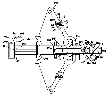
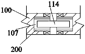
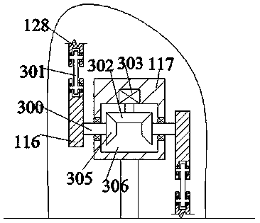

Image

  • Laser light weapon transmitter adopting industrial Internet
  • Laser light weapon transmitter adopting industrial Internet
  • Laser light weapon transmitter adopting industrial Internet

Examples


Embodiment Construction

[0020] All features disclosed in this specification, or steps in all methods or processes disclosed, may be combined in any manner, except for mutually exclusive features and / or steps.

[0021] Any feature disclosed in this specification (including any appended claims, abstract and drawings), unless expressly stated otherwise, may be replaced by alternative features which are equivalent or serve a similar purpose. That is, unless expressly stated otherwise, each feature is one example only of a series of equivalent or similar features.

[0022] like Figure 1-5 As shown, the laser light weapon transmitter of the industrial Internet of the present invention includes a main body 100, and the main body 100 is fixed with an open cavity 103 that penetrates up and down, and the right side of the open cavity 103 is provided with a through cavity 106 located in the main body 100 The front and rear end walls of the through cavity 106 are connected with a chute 105, the upper and lower...


PUM


Abstract

The invention discloses a laser light weapon transmitter adopting industrial Internet. The laser light weapon transmitter comprises a main body. An open cavity penetrating up and down is fixedly arranged in the main body. A penetrating cavity positioned in the main body is arranged on the right side of the open cavity. A sliding chute is arranged at the front and rear end walls of the penetratingcavity in a communicating mode. Vertically symmetric through cavities communicating with exterior space are arranged in the upper and lower end walls of the sliding chute in a communicating mode. A side cavity is arranged in the right end wall of the sliding chute in a communicating mode. The front end wall of the open cavity is provided with a connecting cavity in a communicating mode. The frontend wall of the connecting cavity is provided with an opening facing upwards in a communicating mode. Abutting blocks are slidably arranged in the open cavity. The left end surfaces of the abutting blocks are fixedly provided with a sliding rod. The sliding rod slidably penetrates through the left end wall of the open cavity and extends out of the external space leftwards. The laser light weapon transmitter is simple in structure and convenient to use. Because a multi-tensioning type structure is adopted by the laser light weapon transmitter, high-efficiency tensioning of a crossbow pull ropeis achieved; and meanwhile, because laser positioning is adopted for aiming, the rapid adjustment capability of the laser light weapon transmitter is effectively improved, and the safety factor of personnel is increased.

Description

technical field [0001] The invention relates to the field of weapons, in particular to a laser light weapon transmitter for the industrial internet. Background technique [0002] Light weapons are weapon equipment such as rifles, pistols, and crossbows that produce bullets. Existing light weapon transmitters, such as crossbows, are relatively difficult to install laser generators, and in actual use, due to the frequent use of crossbows. The elastic strength of the pull rope of the crossbow is reduced. If the tension of the rope is not enough in an emergency, it will affect the shooting effect of the weapon and greatly affect the safety of personnel. This device effectively solves this problem. Contents of the invention [0003] The object of the present invention is to provide a laser light weapon transmitter for the industrial Internet, which can overcome the above-mentioned defects of the prior art. [0004] According to the present invention, the laser light weapon tra...

Claims


Application Information

Patent Timeline
Patent Type & Authority Applications(China)
IPC IPC(8): F41B5/14
CPCF41B5/14F41B5/1442
Inventor 王月芳
Owner 王月芳
Learn More