[0017] In order to make the technical means, creative features, objectives and effects achieved by the present invention easy to understand, the present invention will be further explained below in conjunction with specific embodiments.
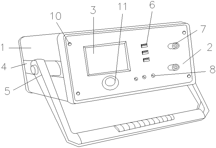
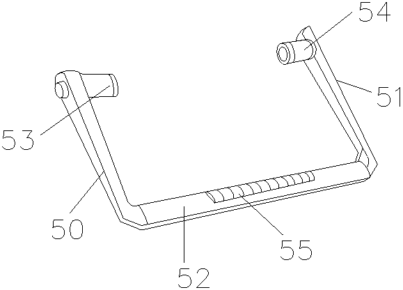
[0018] See Figure 1-Figure 2 , The present invention provides a portable computer conversion device, the structure of which includes a device main body 1, an operation panel 2, a display screen 3, a groove 4, a portable handle 5, a USB interface 6, a conversion access port 7, and a conversion output port 8. The operation panel 2 is electrically fixedly connected to the front end surface of the device main body 1, the display screen 3 is inlaid on the front end surface of the operation panel 2, and both the left and right end surfaces of the device main body 1 are recessed inward to form a groove 4. A portable handle 5 is movably connected to the inner surface of the groove 4, and the portable handle 5 is composed of a left connecting rod 50, a right connecting rod 51, a cross rod 52, a left connecting shaft 53, a right connecting shaft 54, and a non-slip protrusion. 55, the left connecting rod 50, the right connecting rod 51, and the cross rod 52 are integrally formed. The cross rod 52 is vertically connected to the middle of the left connecting rod 50 and the right connecting rod 51, and the left connecting shaft 53 is vertical Connected to the right end surface of the left connecting rod 50, the right connecting shaft 54 is perpendicularly connected to the left end surface of the right connecting shaft 54, the anti-slip protrusions 55 are evenly arranged on the outer surface of the cross rod 52, the USB interface 6 Embedded in the front surface of the operation panel 2, the right end of the USB interface 6 is electrically connected with a conversion access port 7, the front surface of the operation panel 2 is evenly arranged with conversion output ports 8, and the front surface of the operation panel 2 There are fixing screws 10 evenly distributed, the front surface of the operation panel 2 is electrically connected with a power button 11, the fixing screws 10 are a circular structure with a number of 4, and the number of the USB ports 6 is 3-4 , The shape is rectangular, the display screen 3 is a rectangle with a diagonal length of 4 inches, the radius of the conversion output port 7 is 2-4mm, and the shapes of the conversion access port 7 and the conversion output port 8 are both It is round.
[0019] The material of the portable handle mentioned in this patent is green and environmentally friendly, light weight, strong pressure resistance, and easy to disassemble and clean. By using the handle, the user can easily and simply carry the computer conversion device on the body.
[0020] When in use, first check whether each part is firmly connected. After confirming that the equipment is in good condition, place the equipment in a suitable position, connect the conversion access port and conversion output port of the equipment to the computer, and then the equipment can start to work normally.
[0021] The device body-1, operation panel-2, display screen-3, groove-4, portable handle-5, USB interface-6, conversion access port-7, conversion output port-8, left connecting rod of the present invention -50, right connecting rod -51, crossbar -52, left connecting shaft -53, right connecting shaft -54, non-slip protrusion -55, fixing screw-10, power button-11, all parts are common standard parts or this The structure and principle of the components known to those skilled in the art are all known to those skilled in the technical manual or through conventional experimental methods. The problem solved by the present invention is that the prior art cannot easily and simply carry the equipment with them. On the body, the device cannot be moved flexibly according to the change of the working environment, and the practical performance is insufficient. The present invention can easily and conveniently carry the device on the body through the combination of the above components and the portable handle, so as to respond flexibly The needs of various working environments have effectively improved the practical performance of the equipment, as described below:
[0022] A portable handle 5 is movably connected to the inner surface of the groove 4, and the portable handle 5 consists of a left connecting rod 50, a right connecting rod 51, a cross rod 52, a left connecting shaft 53, a right connecting shaft 54, and a non-slip protrusion. 55, the left connecting rod 50, the right connecting rod 51, and the cross rod 52 are integrally formed. The cross rod 52 is vertically connected to the middle of the left connecting rod 50 and the right connecting rod 51, and the left connecting shaft 53 is vertical Connected to the right end surface of the left connecting rod 50, the right connecting shaft 54 is perpendicularly connected to the left end surface of the right connecting shaft 54, and the anti-slip protrusions 55 are evenly arranged on the outer surface of the cross rod 52.
[0023] In Embodiment 1 of the present invention, the number of the USB ports is 3, and the radius of the conversion output port is 2 mm.
[0024]
[0025] In summary, when the number of USB interfaces of the present invention is 4, and the radius of the conversion output port is 4 mm, the compatibility and ease of use of the present invention reach the best state.
[0026] The above shows and describes the basic principles and main features of the present invention and the advantages of the present invention. For those skilled in the art, it is obvious that the present invention is not limited to the details of the above exemplary embodiments, and does not deviate from the spirit or basics of the present invention. In the case of features, the present invention can be implemented in other specific forms. Therefore, from any point of view, the embodiments should be regarded as exemplary and non-limiting. The scope of the present invention is defined by the appended claims rather than the foregoing description, and therefore it is intended to fall within the claims. All changes within the meaning and scope of the equivalent elements of are included in the present invention. Any reference signs in the claims should not be regarded as limiting the claims involved.
[0027] In addition, it should be understood that although this specification is described in accordance with the implementation manners, not each implementation manner only includes an independent technical solution. This narration in the specification is only for clarity, and those skilled in the art should consider the specification as a whole The technical solutions in the embodiments can also be appropriately combined to form other implementations that can be understood by those skilled in the art.