
A test apparatus for use in the field of communications

A test device and technology in the field, applied in transmission monitoring, electrical components, transmission systems, etc., can solve problems such as inconvenient use and increased test costs, and achieve the effects of easy storage, reduced test costs, and easy parts

Inactive Publication Date: 2018-12-18
合肥鸿坤通信工程有限公司
View PDF5 Cites 0 Cited by
  • Summary
  • Abstract
  • Description
  • Claims
  • Application Information

AI Technical Summary

Problems solved by technology

[0002] In the patent name: a communication module testing device, the publication number is: CN203675121U utility model patent, discloses a simple structure, small size, easy to carry testing device; but in this technology, for different heights to be To test the communication module, it is necessary to replace the cover plates of different thicknesses before the communication module to be tested can be clamped and fixed, which makes it necessary to purchase several cover plates with different thicknesses at the same time when purchasing the device, which increases the test cost; in addition, the device When in use, it is necessary to install an adapted cover plate according to the height of the communication module to be tested, resulting in inconvenient use

Method used


Image

  • A test apparatus for use in the field of communications
  • A test apparatus for use in the field of communications

Examples


Embodiment

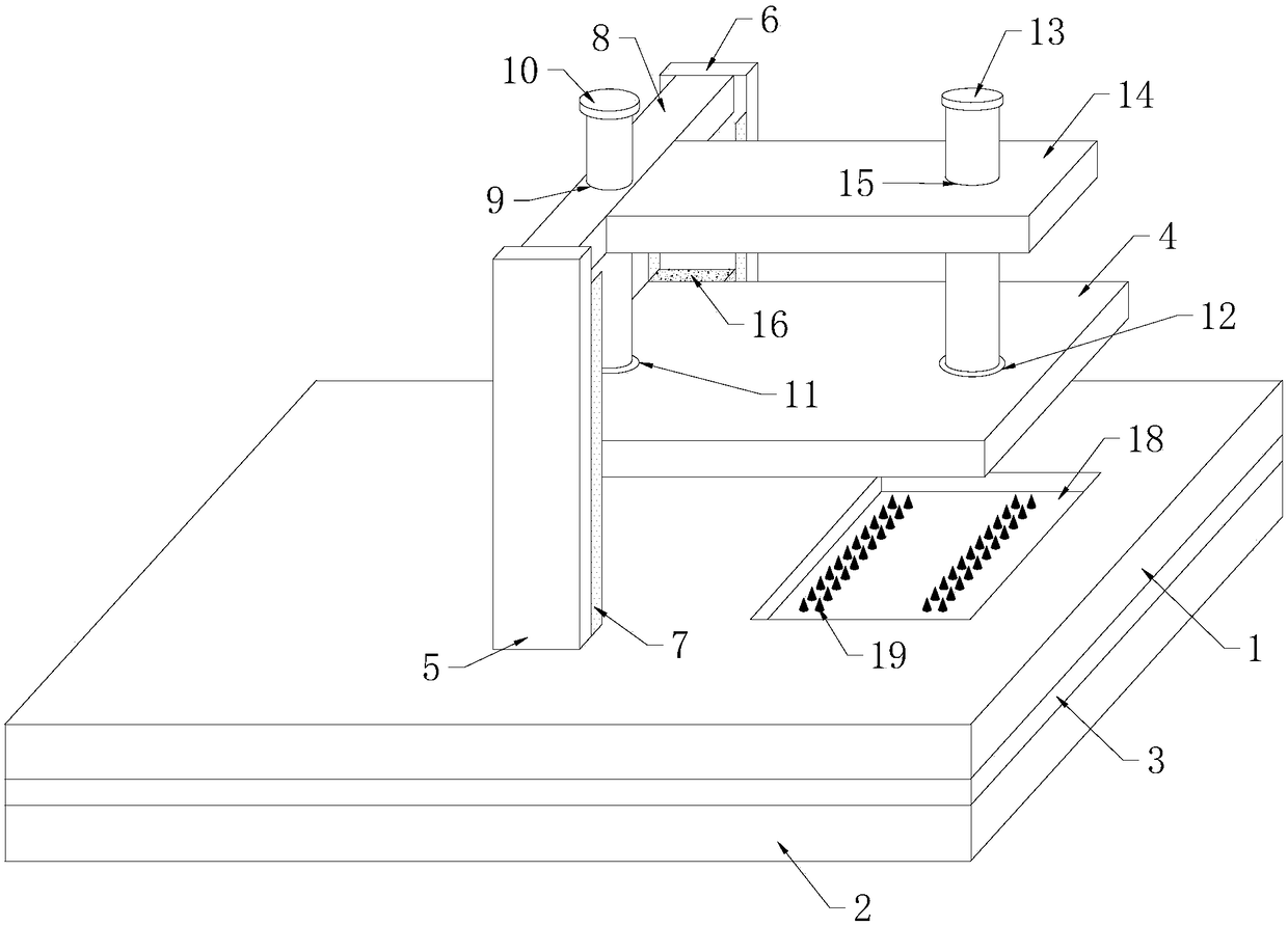
[0021] Example: such as Figure 1-2 As shown, a test device used in the communication field includes a first splint 1, a second splint 2, a test circuit board 3, a cover plate 4 and a fixture, and the test circuit board 3 is clamped on the first splint 1 and the second splint 2, the fixture is located on the upper end surface of the first splint 1;

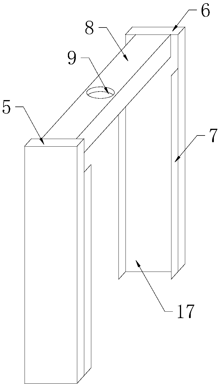
[0022] The fixture is divided into a No. 1 support plate 5 and a No. 2 support plate 6. A baffle plate 7 is installed on both sides of the opposite side of the No. 1 support plate 5 and No. 2 support plate 6, and an adjustment plate 8 is suspended above the baffle plate 7. , the middle part of the adjustment plate 8 is provided with a bolt hole 9, the adjustment bolt 10 extends to the cover plate 4 through the bolt hole 9, and is fixedly clamped in the movable hole 11 embedded in the cover plate 4, and is connected with the movable hole 11 Axial active connection between;

[0023] A clamping hole 12 is embedded in the side of th...


PUM


Abstract

The invention discloses a test device used in the communication field, which comprises a first splint, a second splint, a test circuit board, a cover plate and a fixture. The fixture is divided into No. 1 support plate and No. 2 support plate, A support plate No. 1 and a support No. 2 are provide with a baffle plate, an adjusting plate is suspended above the baffle plate, the middle part of the adjusting plate is provided with bolt holes, An adjust bolt extends through that bolt hole to the cover plate, and fixedly clamped in a movable hole embedded in the cover plate, wherein a clamping holeis embedded in the side of the cover plate far away from the movable hole, the clamping hole fixedly clamps bolts and is axially movably connected with the bolts, the bolts are threaded to connect thethreaded through holes arranged on the suspension plate, and the suspension plate and the adjustment plate are integrally formed and located in the middle of the adjustment plate; The cover plate isdirectly above the bonding pad, and the bonding pad contains a plurality of probes electrically connected with the test circuit, and the test circuit electrically connects with the power module installed inside the test circuit board.

Description

technical field [0001] The invention relates to the technical field of communication engineering, in particular to a test device used in the communication field. Background technique [0002] In the patent name: a communication module testing device, the publication number is: CN203675121U utility model patent, discloses a simple structure, small size, easy to carry testing device; but in this technology, for different heights to be To test the communication module, it is necessary to replace the cover plates of different thicknesses before the communication module to be tested can be clamped and fixed, which makes it necessary to purchase several cover plates with different thicknesses at the same time when purchasing the device, which increases the test cost; in addition, the device When in use, it is necessary to install an adapted cover plate according to the height of the communication module to be tested, resulting in inconvenient use. [0003] Therefore, it is necess...

Claims


Application Information

Patent Timeline
Patent Type & Authority Applications(China)
IPC IPC(8): H04B17/00
CPCH04B17/00
Inventor 李运茹
Owner 合肥鸿坤通信工程有限公司
Learn More