Wood crusher and crushing method

A crusher and crushing mechanism technology, applied in the direction of grain processing, etc., can solve the problems of affecting the work of the crusher, low work efficiency, high processing cost, etc., and achieve the effect of small tool loss, less manpower consumption, and reduced steps

Active Publication Date: 2018-12-21
SOUTH CHINA UNIV OF TECH
View PDF6 Cites 0 Cited by
  • Summary
  • Abstract
  • Description
  • Claims
  • Application Information

AI Technical Summary

Problems solved by technology

[0002] Existing wood crushers use hobs to directly crush logs, but due to the large size of logs, sufficient power is needed to crush logs, so the power required for this kind of wood crusher that directly rolls logs Very large, high energy consumption, and great wear on the tool
In addition, the existing wood shredder adopts a top-mounted feeding port, which requires workers to raise the wood when feeding, and its work efficiency is very low, and it is labor-intensive, and the processing cost is quite high
The broken wood formed after crushing falls freely from the bottom of the machine. If it is not transported away in time, the discharge port will be blocked and the further work of the crusher will be affected.

Method used


Image

  • Wood crusher and crushing method
  • Wood crusher and crushing method
  • Wood crusher and crushing method

Examples


Embodiment 1

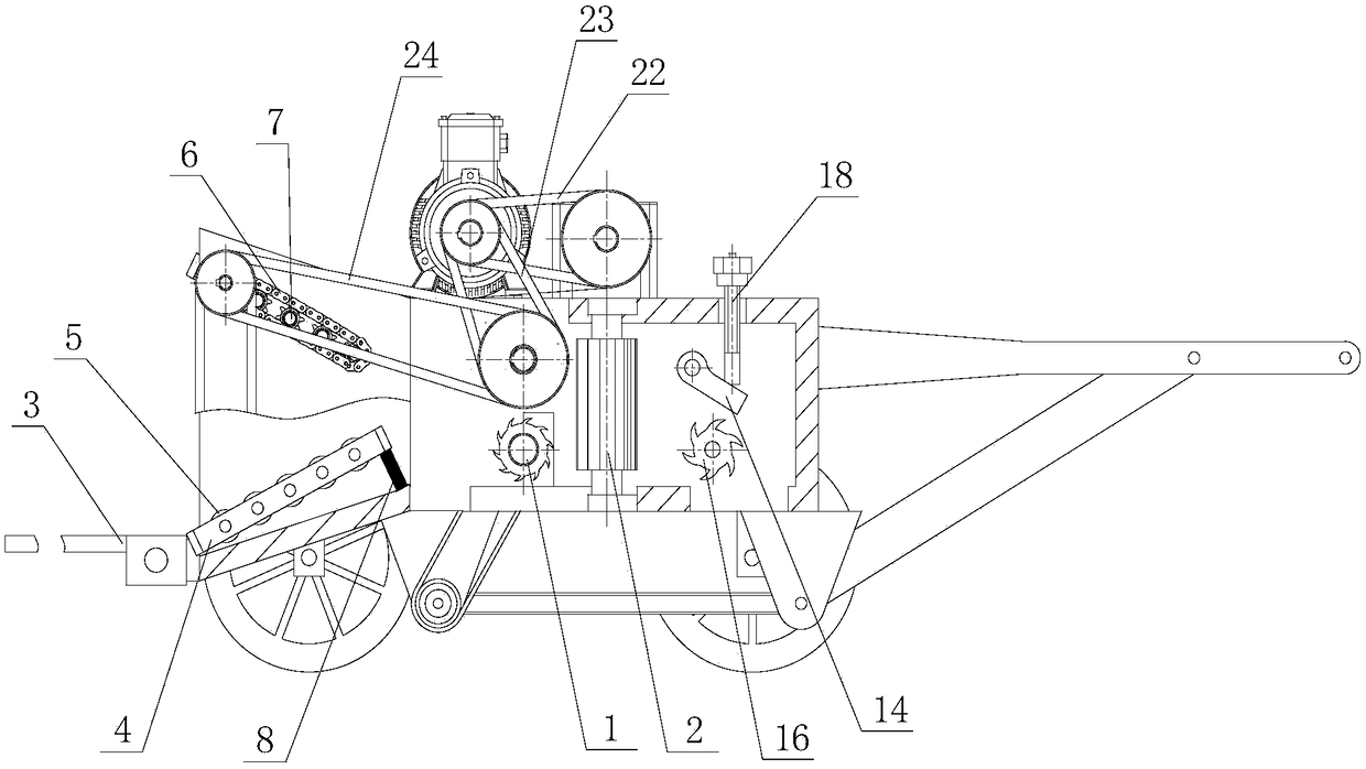
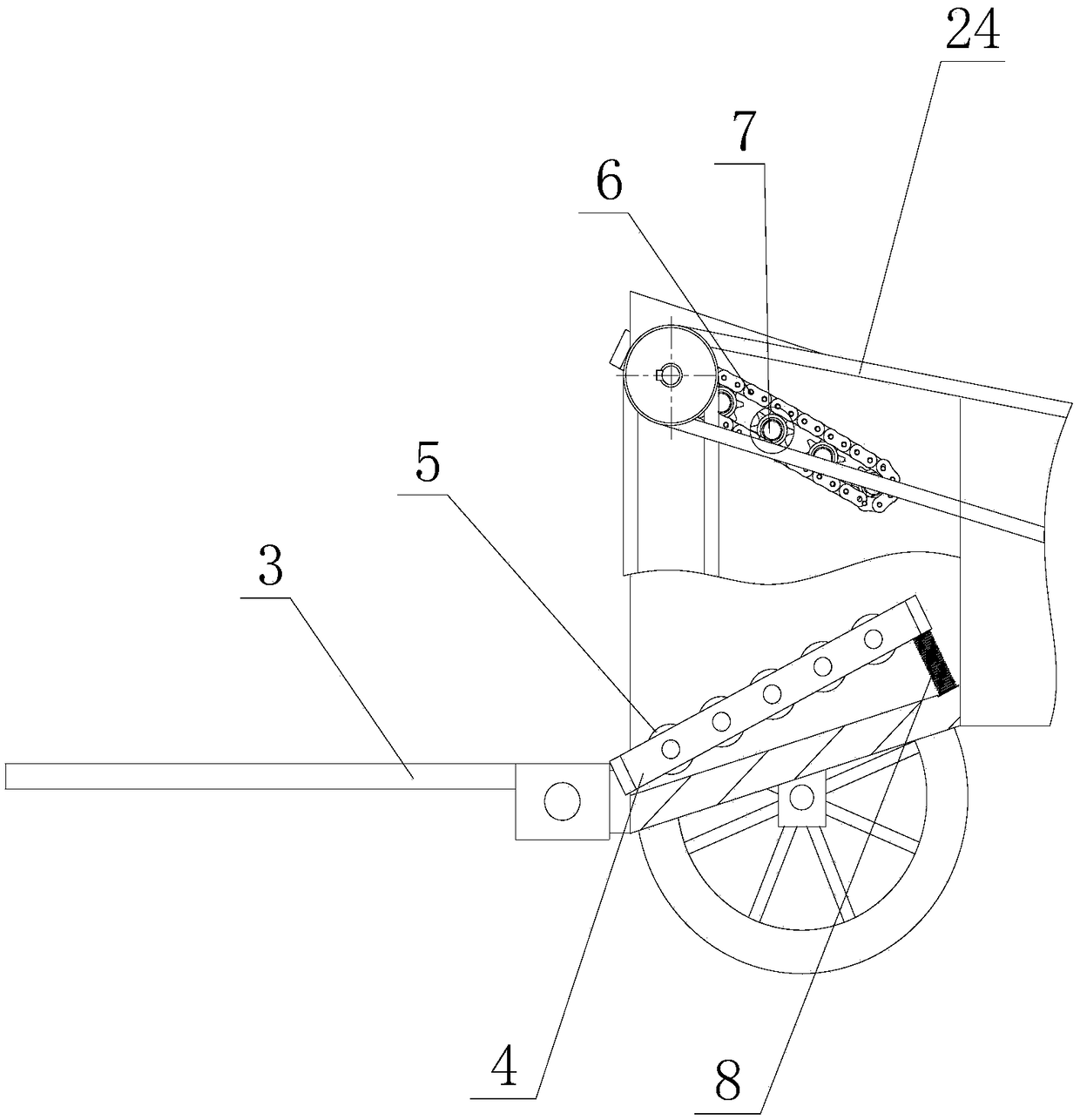
[0033] A wood chipper in this embodiment, such as figure 1As shown, it includes the feeding mechanism, the first crushing mechanism, the second crushing mechanism, the cutting mechanism and the discharging mechanism arranged in sequence along the material conveying direction, and the discharging mechanism is located below the first crushing mechanism, the second crushing mechanism and the cutting mechanism The first crushing mechanism is provided with two matching first hobs, the second crushing mechanism is provided with two matching second hobs, and the first hob and the second hob are vertically arranged; the cutting mechanism Includes matching cutter and baffle. Wherein, each mechanism (including the feeding mechanism, the first crushing mechanism, the second crushing mechanism, the cutting mechanism and the discharging mechanism) is all installed on the frame of the wood crusher. In this embodiment, the material is strip-shaped or stick-shaped logs.

[0034] Such as f...

Embodiment 2

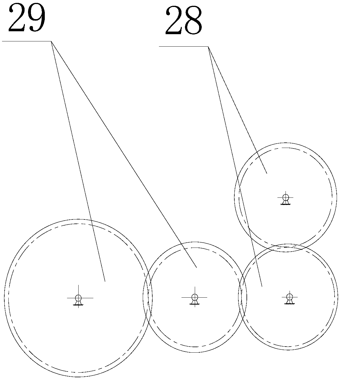
[0045] This embodiment is a kind of wood chipper. Compared with Embodiment 1, the difference is that: the first hob is vertically set (that is, the axis of the first hob is vertical), and the first hob is set between two first hobs. There is a longitudinal first crushing gap; the second hob is arranged horizontally (that is, the axis of the second hob is horizontal), and a transverse second crushing gap is set between the two second hobs.


PUM


Abstract

The invention discloses a wood crusher and crushing method. The crusher comprises a feeding mechanism, a first crushing mechanism, a second crushing mechanism, a cutoff mechanism and a discharging mechanism, all of which are sequentially arranged in the material conveying direction. The discharging mechanism is located below the first crushing mechanism, the second crushing mechanism and the cutoff mechanism. Two cooperating first rolling knives are arranged in the first crushing mechanism, two cooperating second rolling knives are arranged in the second crushing mechanism, and the first rolling knives are perpendicular to the second rolling knives. The cutoff mechanism comprises a cutoff knife and a baffle which cooperates with the cutoff knife. The crushing method comprises the steps that after materials enter the wood crusher through the feeding mechanism, two times of cutting with the cutting directions being perpendicular are firstly carried out through the first crushing mechanism and the second crushing mechanism in sequence, after the cross section of the materials is reduced, the cutoff mechanism carries out chopping treatment, and after chopping treatment is completed, formed crushed wood is conveyed out by the discharging mechanism. By means of the wood crusher and crushing method, the crushing efficiency can be improved, energy consumption is low, meanwhile, tool losses are low, and the service life of a tool can be effectively prolonged.

Description

technical field [0001] The invention relates to the technical fields of mechanical engineering and garden machinery, in particular to a wood crusher and a crushing method for crushing various trees in gardens. Background technique [0002] Existing wood crushers use hobs to directly crush logs, but due to the large size of logs, sufficient power is needed to crush logs, so the power required for this kind of wood crusher that directly rolls logs Very large, high energy consumption, and great wear and tear on the tool. In addition, the existing wood shredder adopts a top-mounted feeding port, and workers need to raise the wood when feeding, which has very low work efficiency, labor-intensive, and high processing costs. The broken wood formed after crushing falls freely from the bottom of the machine. If it is not transported away in time, the discharge port will be blocked and the further work of the crusher will be affected. Contents of the invention [0003] The object ...

Claims


Application Information

Patent Timeline
IPC IPC(8): B02C18/14B02C18/10B02C18/24B02C18/22
CPCB02C18/10B02C18/14B02C18/2216B02C18/2283B02C18/24
Inventor 胡国清陈冠琪李炳耀
Owner SOUTH CHINA UNIV OF TECH
Why Eureka
Try Eureka