
Cleaning equipment

A technology of cleaning equipment and cleaning mechanism, applied in the field of machinery, can solve the problems of poor cleaning effect, high labor intensity and low efficiency, etc.

Pending Publication Date: 2018-12-21
NANJING VOCATIONAL UNIV OF IND TECH
View PDF0 Cites 2 Cited by
  • Summary
  • Abstract
  • Description
  • Claims
  • Application Information

AI Technical Summary

Problems solved by technology

The existing method of scrubbing the container is mainly to manually scrub the container, which is inefficient, labor-intensive, and the cleaning effect is poor. At the same time, the inner wall of the container cannot be scrubbed clean, which cannot meet the needs of daily mechanical processing.

Method used


Image

  • Cleaning equipment
  • Cleaning equipment
  • Cleaning equipment

Examples


Embodiment Construction

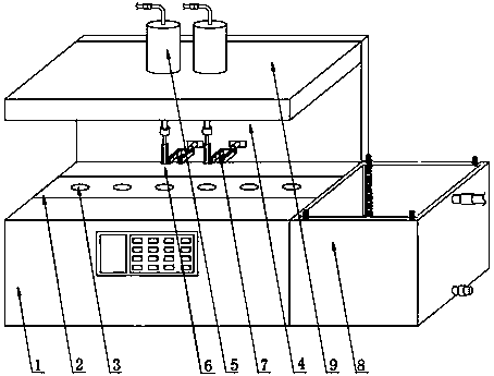
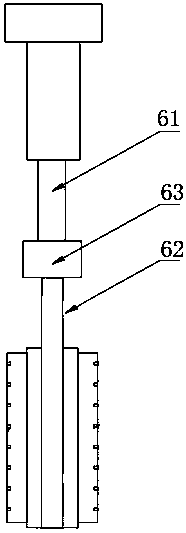
[0021] The cleaning equipment involved in the present invention comprises a horizontally arranged workbench 1 and a conveyor belt 2 horizontally arranged on the workbench 1. The conveyor belt 2 is provided with grooves 3 at intervals, and the center of the groove 3 is connected to the conveyor belt 2. The direction of movement is parallel, the control panel 4, the liquid storage tank 5, the cleaning mechanism 6, the clamping mechanism 7, the vertical plate 4, the top plate 9 and the secondary cleaning mechanism 8. When the conveyor belt 2 is at the initial position, one of the grooves 3 on the conveyor belt 2 is located directly below the cleaning mechanism 6 .

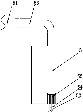
[0022] The top plate 9 is arranged horizontally and parallel to the workbench 1. A vertical plate 4 is arranged between the top plate 9 and the workbench 1. The vertical plate 4 is perpendicular to the top plate 9 and the workbench 1. The liquid storage tank 5 is arranged on the upper surface of the top plate 9. The cl...


PUM


Abstract

The invention discloses cleaning equipment. The cleaning equipment comprises a working table which is arranged horizontally, a conveying belt which is positioned on the upper surface of the working table, liquid storage tanks, a cleaning mechanism, a clamping mechanism which is used for clamping to-be-cleaned containers, a vertical plate and a top plate; and the top plate is parallel to the working table, the vertical plate is arranged between the top plate and the working table in the length direction, the liquid storage tanks are arranged on the upper surface of the top plate, the cleaning mechanism is vertically and downwards arranged on the lower surface of the top plate, the clamping mechanism is horizontally arranged on the vertical plate, and the cleaning mechanism and the clampingmechanism are located above the conveying belt. According to the cleaning equipment, containers in grooves on the conveying belt can be automatically cleaned, manual participation is not needed, a plurality of containers can be cleaned at the same time, and container automatic cleaning is realized.

Description

technical field [0001] The invention relates to the technical field of machinery, in particular to a cleaning device. Background technique [0002] In the daily machining process, different containers need to be used. After a long period of use, the inner wall of the container will be covered with more impurities, and even more dirt will be deposited. Therefore, it is necessary to regularly check the inner wall of the container. scrub. The existing method of scrubbing the container is mainly to manually scrub the container, which has low efficiency, high labor intensity, and poor cleaning effect. At the same time, the inner wall of the container cannot be scrubbed clean, which cannot meet the needs of daily mechanical processing. Therefore, it is necessary to design an automatic cleaning device. Contents of the invention [0003] The technical problem to be solved by the present invention is to provide a cleaning device that realizes the purpose of automatic cleaning wit...

Claims


Application Information

Patent Timeline
Patent Type & Authority Applications(China)
IPC IPC(8): B08B9/36B08B9/32B08B13/00
CPCB08B9/36B08B9/32B08B13/00
Inventor 王文虎余旺旺马忠蕾夏瑜彤申丛珊牛明祥
Owner NANJING VOCATIONAL UNIV OF IND TECH
Features
  • Generate Ideas
  • Intellectual Property
  • Life Sciences
  • Materials
  • Tech Scout
  • Unparalleled Data Quality
  • Higher Quality Content
  • 60% Fewer Hallucinations
Learn More