Cleaning device for electronic rotor

A technology for cleaning devices and motor rotors, applied in cleaning methods and utensils, cleaning methods using tools, chemical instruments and methods, etc., can solve the problems of danger, high labor intensity, poor quality, etc., to save labor costs, clean The effect of good quality and easy operation

Active Publication Date: 2017-05-10
BAOTOU CRRC MOTOR CO LTD
View PDF6 Cites 17 Cited by
  • Summary
  • Abstract
  • Description
  • Claims
  • Application Information

AI Technical Summary

Problems solved by technology

[0003] At present, the cleaning of the motor rotor is mostly manual cleaning, that is, the operator holds the cleaning brush and dips the cleaning solution to clean it. The manual cleaning efficiency is low, and long-term contact with the cleaning agent is not good for the health of the operator. In each position, the operator needs to climb up and down, and manually rotate around the rotor to clean, which is dangerous, labor-intensive, and difficult to guarantee the cleaning quality
[0004] Therefore, how to solve the problems of low cleaning efficiency, poor quality, and high labor intensity of the motor rotor is a technical problem that those skilled in the art need to solve at present.

Method used


Image

  • Cleaning device for electronic rotor
  • Cleaning device for electronic rotor
  • Cleaning device for electronic rotor

Examples


Embodiment Construction

[0026] The core of the present invention is to provide a motor rotor cleaning device, the structural design of which can make the cleaning efficiency of the motor rotor high, the quality good, the pollution small and the labor cost saved.

[0027] In order to enable those skilled in the art to better understand the solution of the present invention, the present invention will be further described in detail below in conjunction with the accompanying drawings and specific embodiments.

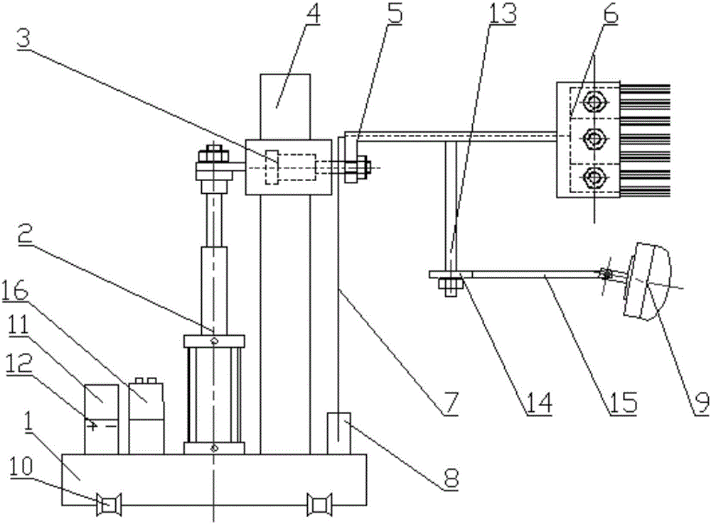
[0028] Please refer to figure 1 , figure 1 It is a structural schematic diagram of a specific embodiment of the motor rotor cleaning device provided by the present invention.

[0029] The motor rotor cleaning device provided by the specific embodiment of the present invention includes a movable carrier 1, a lifting hydraulic cylinder 2 vertically arranged on the carrier 1, and a crossbeam 5 with one end installed on the top of the lifting hydraulic cylinder 2, and the other part of the crossbeam...


PUM


Abstract

The invention discloses a cleaning device for an electronic rotor. The cleaning device comprises a bearing frame, a lifting hydraulic cylinder vertically arranged on the bearing frame and a crossbeam with one end mounted at the top of the lifting hydraulic cylinder, and a cleaning brush is mounted at the other end of the crossbeam. The cleaning device further comprises a cleaning agent supply module and a liquid conveying pipeline used for conveying a cleaning agent to the cleaning brush. When the cleaning device is in use, the lifting hydraulic cylinder is started to move the cleaning brush to a required height and to enable the cleaning brush to be in contact with the surface of the rotor, then the cleaning agent supply module is started to enable the cleaning agent to fully infiltrate the cleaning brush through the liquid conveying pipeline, after that, the bearing frame is moved to enable the cleaning device to conduct circular motion around the rotor, and after a round, the cleaning brush is enabled to ascend or descend for a certain distance through the lifting hydraulic cylinder to repeat the actions till cleaning of the surface of the whole rotor is finished. The cleaning device for the motor rotor, provided by the invention, is convenient to operate, can realize automatic cleaning of the rotor, is high in cleaning efficiency, good in cleaning quality and low in pollution, can lower the manual cost, and is particularly suitable for cleaning the surface of the large-scale motor rotor.

Description

technical field [0001] The invention relates to the field of motor rotor cleaning, in particular to an electronic rotor cleaning device. Background technique [0002] The motor rotor is an important part of the motor. Before the permanent magnet is pasted on the electronic rotor, it is usually necessary to clean the grease, dirt, etc. on its surface to make it meet the required cleanliness and reduce the rotor and other parts after assembly. friction and wear, and prolong service life. [0003] At present, the cleaning of the motor rotor is mostly manual cleaning, that is, the operator holds the cleaning brush and dips the cleaning solution to clean it. The manual cleaning efficiency is low, and long-term contact with the cleaning agent is not good for the health of the operator. At each position of the machine, the operator needs to climb up and down, and manually rotate around the rotor for cleaning, which is dangerous, labor-intensive, and difficult to guarantee the clea...

Claims


Application Information

Patent Timeline
Patent Type & Authority Applications(China)
IPC IPC(8): B08B1/00
CPCB08B1/002B08B1/006
Inventor 杜刚张海平赵艳
Owner BAOTOU CRRC MOTOR CO LTD
Why Eureka
Try Eureka