Riveting mechanism capable of achieving multi-rivet simultaneous riveting
A riveting mechanism and riveting technology, applied in the field of riveting, can solve problems such as unsatisfactory riveting efficiency and lower production efficiency, and achieve the effect of improving riveting efficiency and improving production efficiency
- Summary
- Abstract
- Description
- Claims
- Application Information
AI Technical Summary
Problems solved by technology
Method used
Image

Examples
Embodiment Construction
[0017] The following will clearly and completely describe the technical solutions in the embodiments of the present invention with reference to the accompanying drawings in the embodiments of the present invention. Obviously, the described embodiments are only some, not all, embodiments of the present invention.
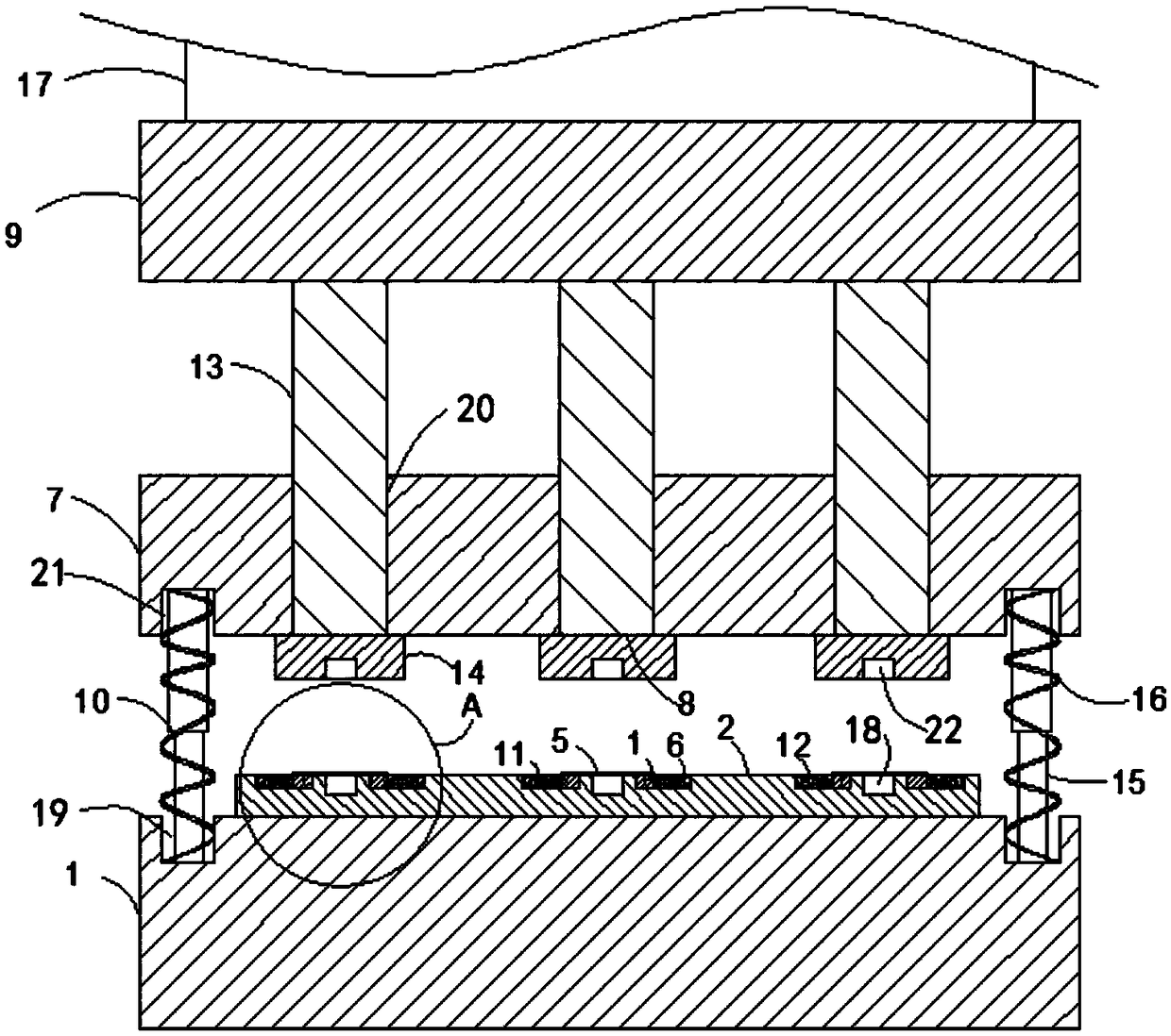
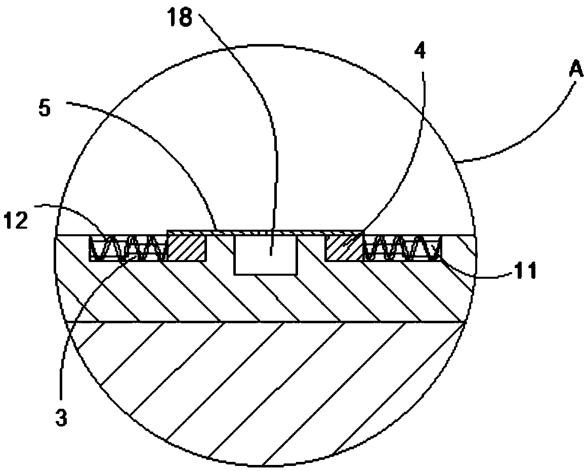
[0018] refer to Figure 1-2 , a riveting mechanism for simultaneously riveting multiple nails, comprising a base 1, the upper end of the base 1 is fixedly connected with a placement plate 2, the upper end of the placement plate 2 is provided with a plurality of first placement grooves 18, and the plurality of first placement grooves 18 The left and right ends are provided with chute 3, and the two chute 3 are equipped with matching sliders 4, the upper ends of the two sliders 4 are fixedly connected with splints 5, and the opposite side walls of the two splints 5 In contact with each other, one end of the splint 5 is fixedly connected with a rubber strip, the rubber ...
PUM
 Abstract
Description
Claims
Application Information
 - Generate Ideas
- Intellectual Property
- Life Sciences
- Materials
- Tech Scout
- Unparalleled Data Quality
- Higher Quality Content
- 60% Fewer Hallucinations
Browse by: Latest US Patents, China's latest patents, Technical Efficacy Thesaurus, Application Domain, Technology Topic, Popular Technical Reports.
© 2025 PatSnap. All rights reserved.Legal|Privacy policy|Modern Slavery Act Transparency Statement|Sitemap|About US| Contact US: help@patsnap.com