Fixture for welding electronic component

A technology of electronic components and fixtures, applied in welding equipment, auxiliary welding equipment, welding/cutting auxiliary equipment, etc., can solve the problems of adjusting the distance between welding table and fixture, affecting the welding accuracy of electronic components, and unable to fix electronic components , to increase the stability of the

Inactive Publication Date: 2018-12-21
绍兴市柯桥区蓝天软件有限公司
View PDF0 Cites 2 Cited by
  • Summary
  • Abstract
  • Description
  • Claims
  • Application Information

AI Technical Summary

Problems solved by technology

[0004] Aiming at the deficiencies of the prior art, the present invention provides a jig for welding electronic components, which has the advantages of strong adaptability and improved precision, and solves the problem that most jigs for welding electronic components cannot be used according to the electronic

Method used


Image

  • Fixture for welding electronic component
  • Fixture for welding electronic component
  • Fixture for welding electronic component

Examples


Example Embodiment

[0018] The technical solutions in the embodiments of the present invention will be clearly and completely described below in conjunction with the accompanying drawings in the embodiments of the present invention. Obviously, the described embodiments are only a part of the embodiments of the present invention, rather than all the embodiments. Based on the embodiments of the present invention, all other embodiments obtained by those of ordinary skill in the art without creative work shall fall within the protection scope of the present invention.
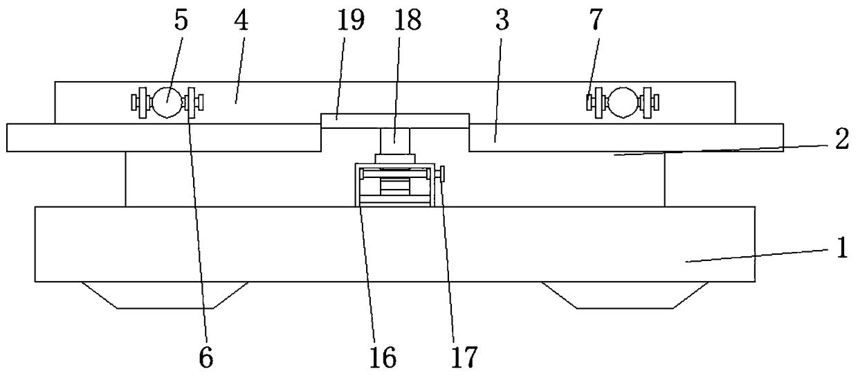
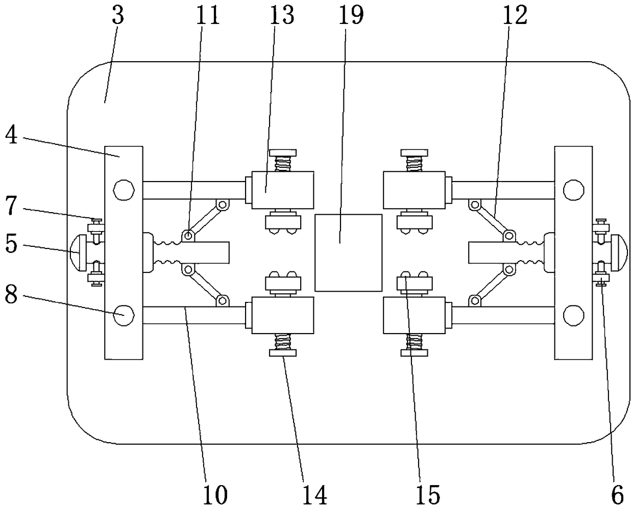
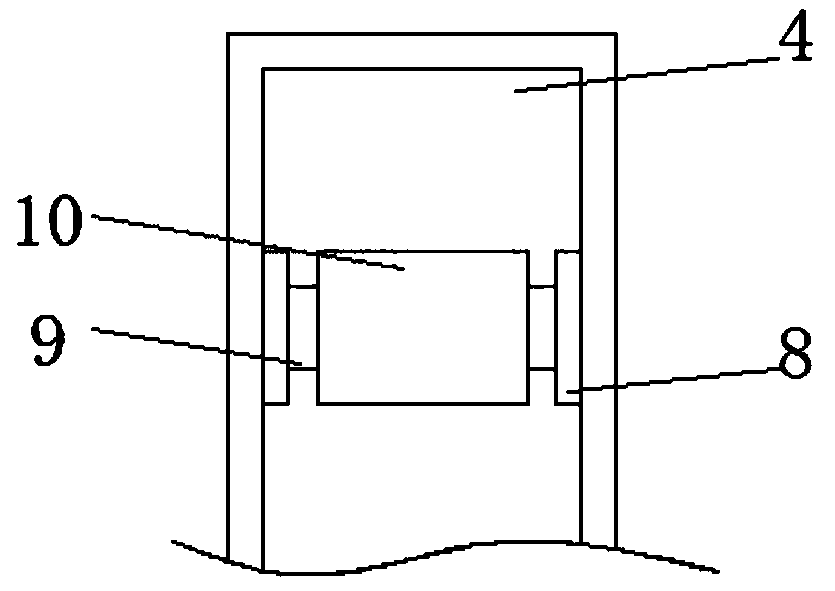
[0019] See Figure 1-3 , A fixture for welding electronic components, including a support base 1. Through the support base 1, the stability of the electronic components during welding is increased. The support plate 4 is used to prevent the support rod 5 from shaking back and forth during movement. As a result, the limit block 11 and the limit plate 12 are shaken, and the electronic components cannot be clamped. The top of the support ba...


PUM

PropertyMeasurementUnit
Thicknessaaaaaaaaaa

Abstract

The invention relates to the technical field of welding fixtures, and discloses a fixture for welding an electronic component. The fixture comprises a support base of which the top is fixedly connected to support blocks, and the top of each support block is fixedly connected to a support frame of which the top is fixedly connected to a support plate; the side of each support plate is slidably connected to a support rod of which one end penetrates through and extends to the outside of the corresponding support plate; and the side of each support plate is further fixedly connected to transverseplates located on the both sides of the corresponding support rod. Through the effect of the support plates, the situation that the support rods are shaken back and forth and consequently stop blocksand stop plates are shaken so that the electronic component can not be clamped is avoided; through the effect of cross rods, the support rods are fixed directly after the electronic component is clamped, and the situation that the support rods are moved again after being stresses and consequently the electronic component is loosened from a limiting clamp is avoided; and the problem that the position is changed when the electronic component is stressed, and consequently the welding accuracy of the electronic component is affected is solved.

Description

technical field [0001] The invention relates to the technical field of welding fixtures, in particular to a fixture for welding electronic components. Background technique [0002] Fixtures usually consist of positioning elements, clamping devices, tool setting guide elements, and indexing devices to enable the workpiece to complete the processing of several stations in one installation. There are two types of rotary indexing devices and linear moving indexing devices, connecting elements and It is composed of clamp body, clamp base and so on. [0003] Electronic components are usually composed of many small parts to be welded. Most of the existing electronic component welding fixtures cannot adjust the distance between the welding table and the fixture according to the size of the electronic components during use, resulting in excessive Small electronic components cannot be fixed, and when the electronic components are stressed, their positions change, which affects the we...

Claims


Application Information

Patent Timeline
IPC IPC(8): B23K37/04
CPCB23K37/0443B23K37/0461
Inventor 毛资政毛中水
Owner 绍兴市柯桥区蓝天软件有限公司
Why Eureka
Try Eureka