Pipe rack convenient to transport for civil engineering

A pipe fitting placement rack and civil engineering technology, applied in the field of pipe fitting placement racks, can solve problems such as affecting construction, shrinking construction sites, inconvenient movement, etc., and achieve the effects of improving stability, saving resources, and facilitating transportation

Inactive Publication Date: 2018-12-21
GUIZHOU UNIV
View PDF5 Cites 2 Cited by
  • Summary
  • Abstract
  • Description
  • Claims
  • Application Information

AI Technical Summary

Problems solved by technology

[0002] With the development of the times and the advancement of science and technology, civil engineering has attracted much attention. Civil engineering refers to the planning, construction and maintenance of all infrastructure related to water, soil and culture. General civil engineering projects include: roads, Water conservancy, drainage, disaster prevention engineering and transportation, etc. At present, in the construction process, various types of steel pipes or pipes and other pipe fittings are often used. The diameters and lengths of these steel pipes or pipes are different. Placing it in the site will not only occupy a large amount of construction ground, resulting in the shrinkage of the construction site, but also affect the construction and increase the burden on the construction personnel. When the existing pipe fittings are stored or placed, they are generally placed on the ground first. Then stack the pipe fittings on the square wood for easy access. This way the parts take up a lot of space, and because the pipes are of different lengths, it is not convenient to classify and place the pipes, or place the pipe fittings on the rack , but the pipe fitting rack is inconvenient to move when placing the pipe fittings, and the pipe fittings are easy to slip off during the moving process. Therefore, those skilled in the art provide a pipe fitting rack for civil engineering that is easy to transport to solve the above-mentioned background technology proposed question

Method used


Image

  • Pipe rack convenient to transport for civil engineering
  • Pipe rack convenient to transport for civil engineering
  • Pipe rack convenient to transport for civil engineering

Examples


Embodiment Construction

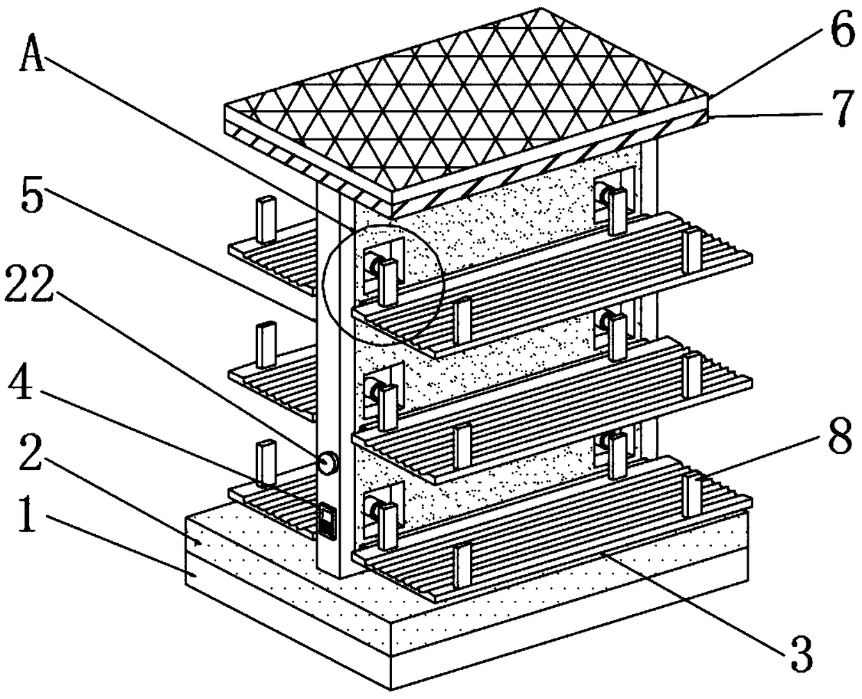
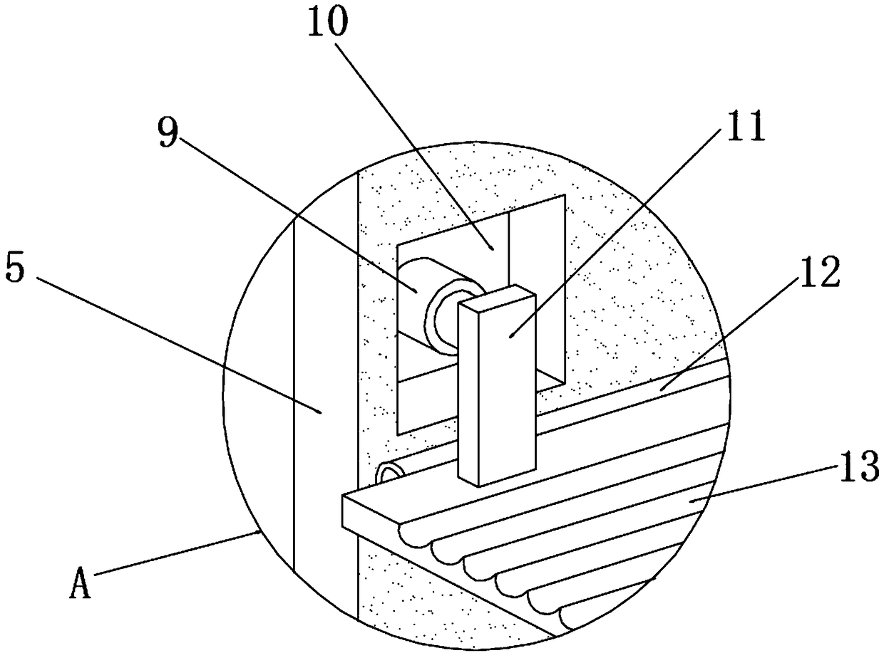
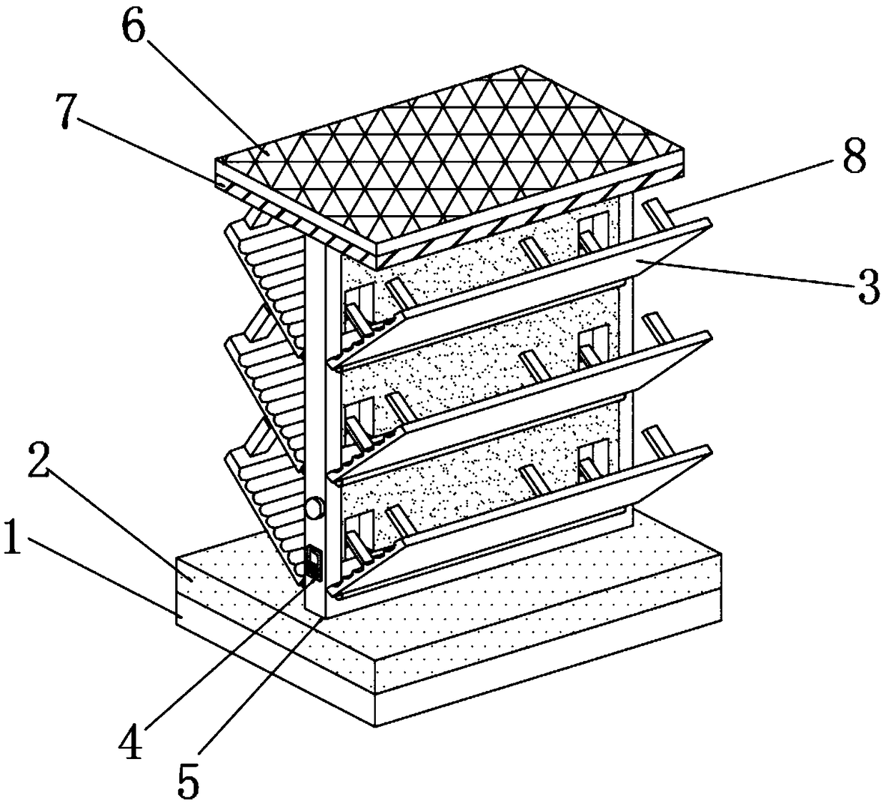
[0016] see Figure 1~4 , in the embodiment of the present invention, a kind of pipe fittings placement rack for civil engineering that is convenient for transportation includes a bottom plate 1, the upper end of the bottom plate 1 is fixedly connected with a base 2, the upper end of the base 2 is equipped with a fixed plate 5, and the base 2 The upper end is located on both sides of the fixed plate 5, and the placement frame 3 is correspondingly installed. The upper end of the base 2 is located on the side of the fixed plate 5, and the controller 4 is fixedly installed. The side of the fixed plate 5 is located above the controller 4. Embedded with an alarm 22, the top of the fixed plate 5 is fixedly connected with an upper cover 7, and the upper surface of the upper cover 7 is fixedly connected with a solar cell panel 6, and the solar cell panel 6 and the upper cover 7 are fixedly connected by bolts, and The solar panel 6 is a rectangular structure, and the upper surface of th...


PUM


Abstract

The invention discloses a pipe rack convenient to transport for civil engineering, comprising a bottom plate. The upper end of the bottom plate is fixedly connected with a base, a fixed plate is installed at the upper end of the base, and a rack is correspondingly mounted at the upper end of the base on two sides of the fixed plate. The invention improves the traditional pipe rack, so that the angle of the rack can be tilted, and pipes can be better protected by the rack; the bottom plate of the rack can be monitored at any time through a pressure sensor and an electronic level, if a gravity difference between two sides of the bottom plate is found to be larger or the bottom plate is inclined, an alarm can be sent out in time to remind staff to adjust the rack; it can be transported by using a storage pulley , and the stability of the rack cannot be affected. According to the design, the structure is novel, the operation is simple and rapid, the stability of the pipe rack is improved,and transportation is facilitated.

Description

technical field [0001] The invention relates to the technical field of civil engineering, in particular to a pipe fitting rack for civil engineering which is convenient for transportation. Background technique [0002] With the development of the times and the advancement of science and technology, civil engineering has attracted much attention. Civil engineering refers to the planning, construction and maintenance of all infrastructure related to water, soil and culture. General civil engineering projects include: roads, Water conservancy, drainage, disaster prevention engineering and transportation, etc. At present, in the construction process, various types of steel pipes or pipes and other pipe fittings are often used. The diameters and lengths of these steel pipes or pipes are different. Placing it in the site will not only occupy a large amount of construction ground, resulting in the shrinkage of the construction site, but also affect the construction and increase the...

Claims


Application Information

Patent Timeline
Patent Type & Authority Applications(China)
IPC IPC(8): B25H3/04
CPCB25H3/04
Inventor 郭仔翔杜斌张玉涛车小林沈明轩
Owner GUIZHOU UNIV
Why Eureka
Try Eureka