An easy-to-adjust transfer device for instrumentation
A transfer device and instrumentation technology, which is applied in the direction of transportation and packaging, trolley accessories, multi-axis trolleys, etc., can solve the problems that it is difficult to meet the needs of people of different heights, no anti-shock measures, instrumentation vibration, etc., to achieve easy maintenance and repair, Low manufacturing and maintenance costs, safe and reliable performance
- Summary
- Abstract
- Description
- Claims
- Application Information
AI Technical Summary
Problems solved by technology
Method used
Image
Examples
Embodiment 1
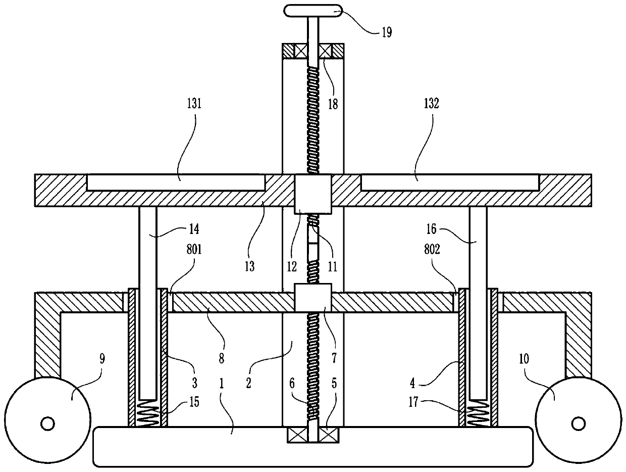
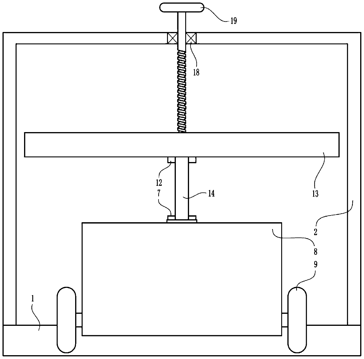
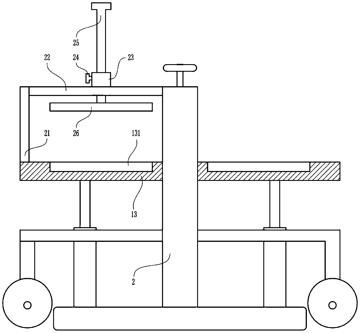
[0022] An easily adjustable transfer device for instrumentation, such as Figure 1-5As shown, it includes a base 1, a gantry plate 2, a first large casing 3, a second large casing 4, a first bearing 5, a first screw 6, a first nut 7, a concave plate 8, a first Roller 9, Second Roller 10, Second Screw Mandrel 11, Second Nut 12, Supporting Plate 13, First Lifting Rod 14, First Big Spring 15, Second Lifting Rod 16, Second Big Spring 17, Second Bearing 18 and rotating wheel 19, the gantry plate 2 is located above the base 1, the gantry plate 2 is connected with the middle position of the top of the base 1, the left side of the top of the base 1 is connected with the first large casing 3, and the right side of the top of the base 1 is connected There is a second large casing 4, the first bearing 5 is embedded in the middle of the top of the base 1, the lower end of the first screw 6 and the first bearing 5 are set in an interference connection, and the first nut 7 is set on the fir...
Embodiment 2
[0024] An easily adjustable transfer device for instrumentation, such as Figure 1-5 As shown, it includes a base 1, a gantry plate 2, a first large casing 3, a second large casing 4, a first bearing 5, a first screw 6, a first nut 7, a concave plate 8, a first Roller 9, Second Roller 10, Second Screw Mandrel 11, Second Nut 12, Supporting Plate 13, First Lifting Rod 14, First Big Spring 15, Second Lifting Rod 16, Second Big Spring 17, Second Bearing 18 and rotating wheel 19, the gantry plate 2 is located above the base 1, the gantry plate 2 is connected with the middle position of the top of the base 1, the left side of the top of the base 1 is connected with the first large casing 3, and the right side of the top of the base 1 is connected There is a second large casing 4, the first bearing 5 is embedded in the middle of the top of the base 1, the lower end of the first screw 6 and the first bearing 5 are set in an interference connection, and the first nut 7 is set on the fi...
Embodiment 3
[0027] An easily adjustable transfer device for instrumentation, such as Figure 1-5 As shown, it includes a base 1, a gantry plate 2, a first large casing 3, a second large casing 4, a first bearing 5, a first screw 6, a first nut 7, a concave plate 8, a first Roller 9, Second Roller 10, Second Screw Mandrel 11, Second Nut 12, Supporting Plate 13, First Lifting Rod 14, First Big Spring 15, Second Lifting Rod 16, Second Big Spring 17, Second Bearing 18 and rotating wheel 19, the gantry plate 2 is located above the base 1, the gantry plate 2 is connected with the middle position of the top of the base 1, the left side of the top of the base 1 is connected with the first large casing 3, and the right side of the top of the base 1 is connected There is a second large casing 4, the first bearing 5 is embedded in the middle of the top of the base 1, the lower end of the first screw 6 and the first bearing 5 are set in an interference connection, and the first nut 7 is set on the fi...
PUM
 Abstract
Description
Claims
Application Information
 - R&D
- Intellectual Property
- Life Sciences
- Materials
- Tech Scout
- Unparalleled Data Quality
- Higher Quality Content
- 60% Fewer Hallucinations
Browse by: Latest US Patents, China's latest patents, Technical Efficacy Thesaurus, Application Domain, Technology Topic, Popular Technical Reports.
© 2025 PatSnap. All rights reserved.Legal|Privacy policy|Modern Slavery Act Transparency Statement|Sitemap|About US| Contact US: help@patsnap.com


