

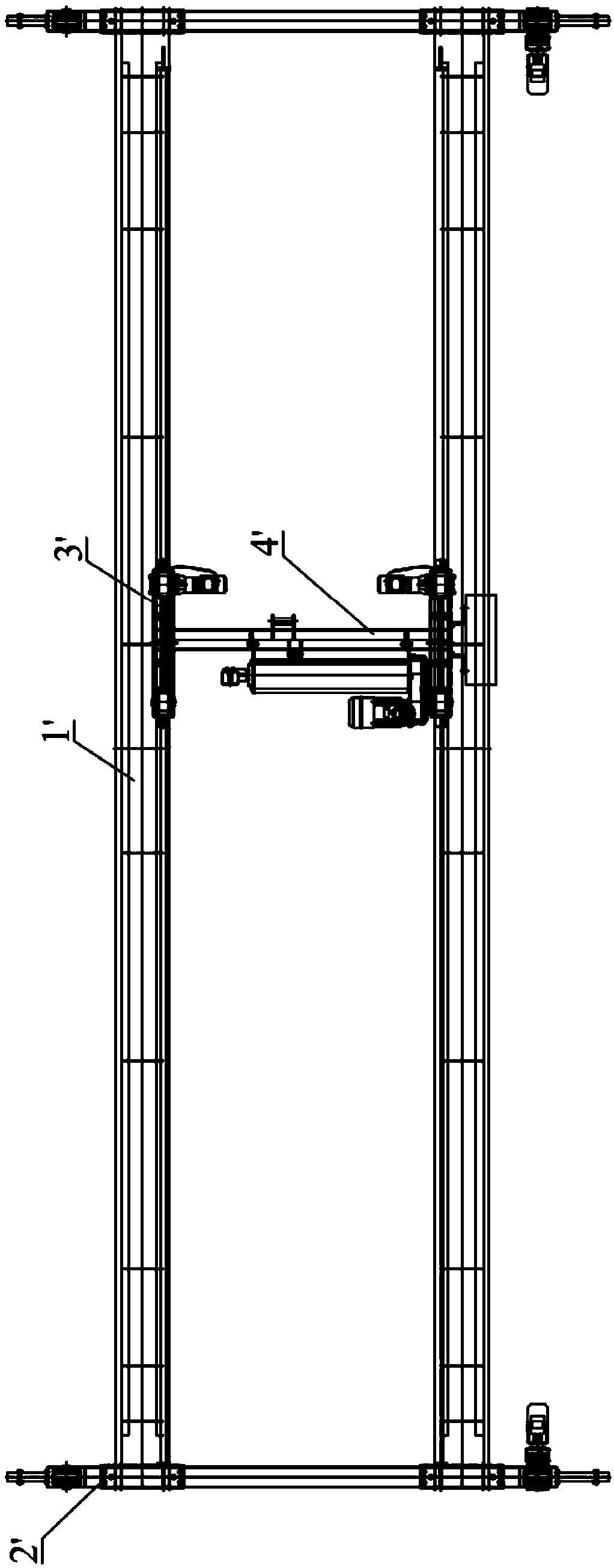
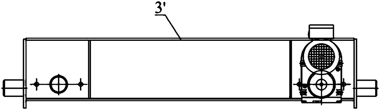
Rail-gnawing preventing end beam device and hoisting equipment
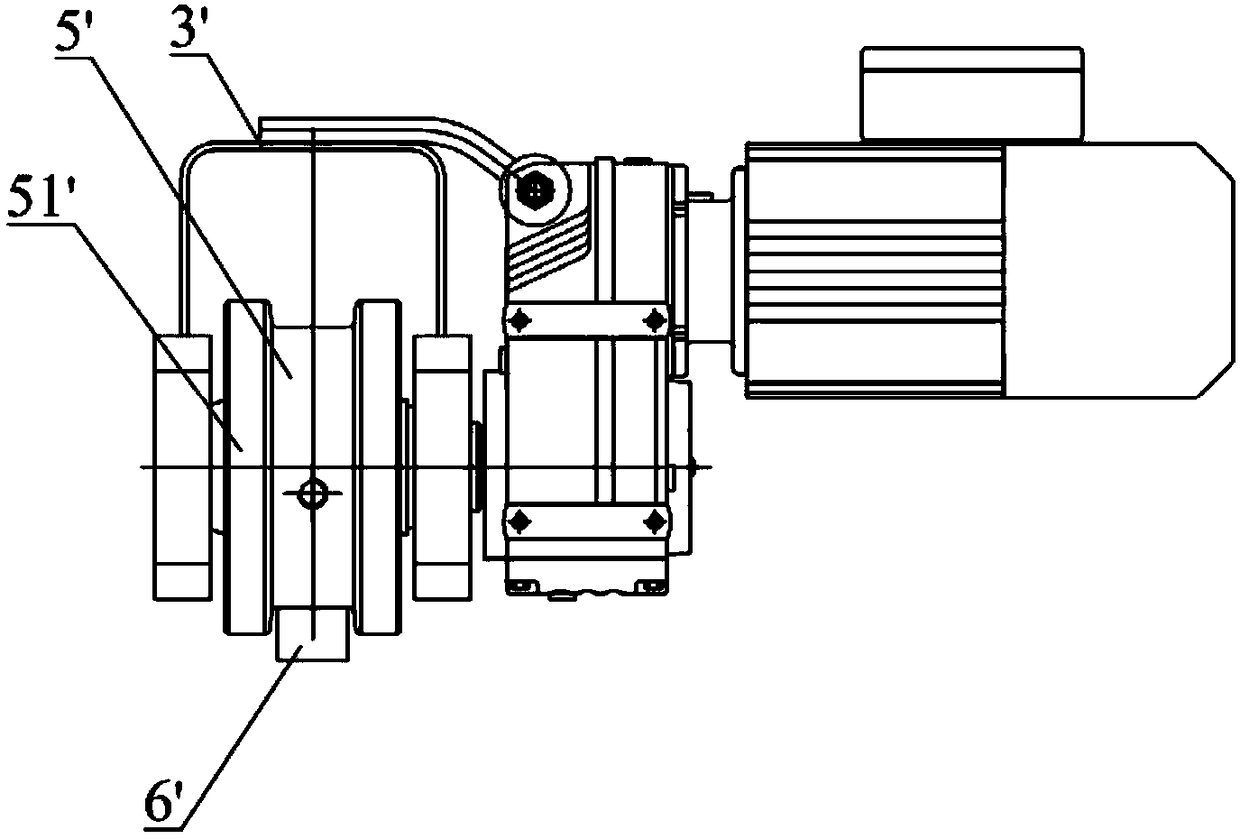
A rail end and anti-gnawing technology, which is applied in the directions of transportation and packaging, running mechanism, load suspension components, etc., can solve the wear and tear of the accelerated rail 6' and the wheel 5', the installation error of the rail 6', and the manufacture of the end beam device 3' Problems such as installation errors to achieve the effect of preventing rail gnawing
- Summary
- Abstract
- Description
- Claims
- Application Information
AI Technical Summary
Problems solved by technology
Method used
Image

Examples
Embodiment Construction
[0033] In order to make the technical problems solved by the present invention, the technical solutions adopted and the technical effects achieved clearer, the technical solutions of the present invention will be further described below in conjunction with the accompanying drawings and through specific implementation methods. It should be understood that the specific embodiments described here are only used to explain the present invention, but not to limit the present invention. In addition, it should be noted that, for the convenience of description, only the parts related to the present invention are shown in the drawings but not all of them.
[0034] In the existing lifting equipment, due to the influence of comprehensive factors such as uneven gravity distribution, asynchronous running motors on both sides of the end beams, track installation errors, and end beam fabrication and installation errors when the trolleys carry materials, the bridge frame or trolleys are in the ...
PUM
 Abstract
Description
Claims
Application Information