
A micro-deformation detection device for a double-girder crane trolley

A double-girder crane and detection device technology, which is applied in the direction of transportation and packaging, load hanging components, etc., can solve the problems affecting the accuracy of the detection device, trolley longitudinal, beam deformation, data errors, etc., to achieve simple structure and avoid gnawing Rail, the effect of easy installation

Active Publication Date: 2022-03-18
河南工学院
View PDF10 Cites 0 Cited by
  • Summary
  • Abstract
  • Description
  • Claims
  • Application Information

AI Technical Summary

Problems solved by technology

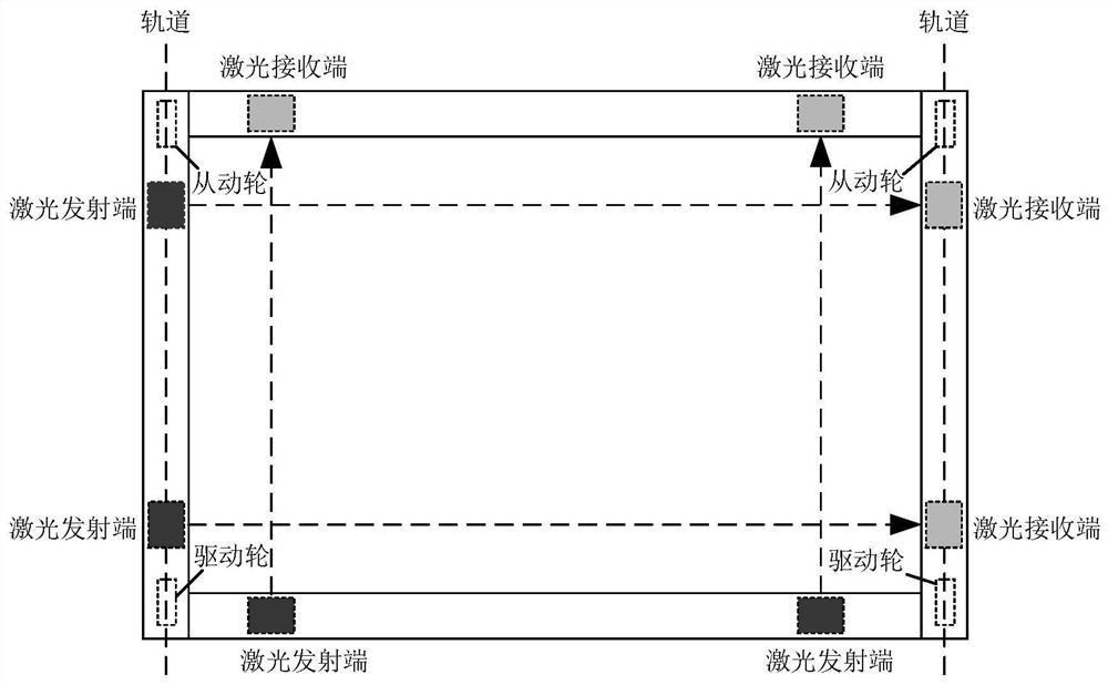
[0007] However, as mentioned above, figure 1 The span between the driving wheel and the driven wheel of the crane trolley is relatively large. When the user uses it, if there are many goods loaded, it is easy to cause deformation of the longitudinal and beams of the trolley, so that the data received by the laser receiver If there is a mistake, misjudgment will occur, which will affect the accuracy of the detection device; some crane manufacturers have improved the operating performance of the crane by increasing the strength of the crane trolley, but they still cannot fundamentally change the phenomenon of the crane trolley gnawing on the rails.

Method used


Image

  • A micro-deformation detection device for a double-girder crane trolley
  • A micro-deformation detection device for a double-girder crane trolley
  • A micro-deformation detection device for a double-girder crane trolley

Examples


Embodiment Construction

[0037] The following will clearly and completely describe the technical solutions in the embodiments of the present invention with reference to the drawings in the embodiments of the present invention. Apparently, the described embodiments are only some of the embodiments of the present invention, but not all of them. Based on the embodiments of the present invention, all other embodiments obtained by persons of ordinary skill in the art without making creative efforts belong to the protection scope of the present invention.

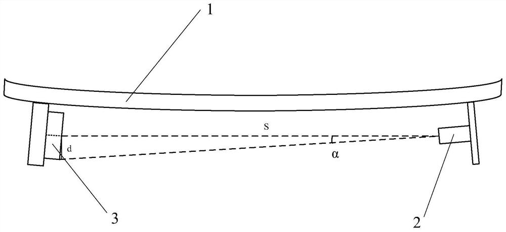
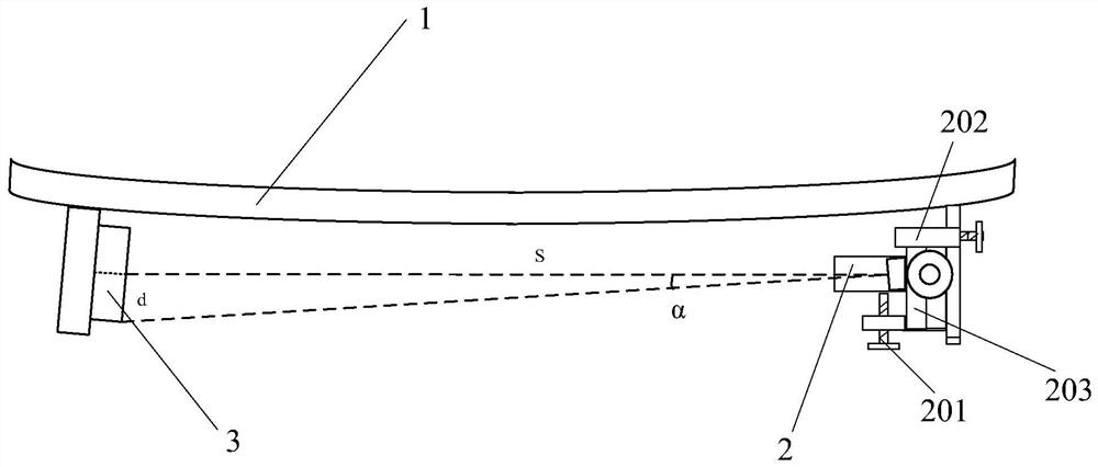
[0038] as attached figure 1 shown, with figure 1 It is a structural schematic diagram of a micro-deformation detection device for a double-girder crane trolley according to one embodiment of the present invention. The micro-deformation detection device for a double-girder crane trolley according to the present invention includes: steel beams installed on each side of the double-girder crane trolley 1. Laser transmitter 2 and photosensitive receiving do...


PUM


Abstract

The patent of the present invention belongs to the field of double-girder crane devices, and specifically discloses a micro-deformation detection device for a double-girder crane trolley, including: laser transmitters and photosensitive receiving lattices respectively installed at both ends of the steel beams on each side of the double-girder crane trolley. The photosensitive receiving dot matrix includes a plurality of photosensitive triodes, and the photosensitive triodes are connected with a microcontroller through an interface circuit; the interface circuit is an AND circuit connected in parallel by a plurality of diodes; the microcontroller according to the According to the laser light signal received by the photosensitive receiving dot matrix, the position information of multiple laser irradiation points is obtained; and according to the position information and the distance between adjacent photosensitive three-stage tubes, the offset distance information of the corresponding laser irradiation point is obtained; and according to The offset distance information obtains the offset angle information of the corresponding laser irradiation point. Through the above technical proposal, the present invention accurately detects the micro-deformation of the double-girder crane trolley, and avoids the rail gnawing phenomenon of the crane trolley.

Description

technical field [0001] The patent of the present invention relates to the field of double-girder crane devices, in particular to a micro-deformation detection device for a double-girder crane trolley. Background technique [0002] Double-girder cranes generally refer to double-girder bridge cranes. Double-girder bridge cranes are important tools and equipment for mechanization and automation of the production process in modern industrial production and lifting transportation. Therefore, double-girder bridge cranes are widely used in indoor and outdoor industrial and mining enterprises, It is widely used in iron and steel chemical industry, railway transportation, port terminals and logistics turnover and other departments and places. As a commonly used large-tonnage hoisting machinery, double-girder cranes occupy an important position in the hoisting industry. [0003] Double-girder cranes are generally composed of three major parts: mechanical, electrical and metal structu...

Claims


Application Information

Patent Timeline
Patent Type & Authority Patents(China)
IPC IPC(8): B66C13/16
CPCB66C13/16
Inventor 仝战营毛景魁刘海华岳俊丽朱研雯许留同何华芳李希庆李文君鲍振伟佘凯
Owner 河南工学院
Learn More