Road soil filling and compacting device

A compaction device and soil technology, applied in the direction of roads, roads, road repair, etc., can solve the problems of inconvenient road compaction effect, large volume of road compaction equipment, and inability to move flexibly.

Active Publication Date: 2018-12-21
临清市中科建工程有限公司
View PDF7 Cites 5 Cited by
  • Summary
  • Abstract
  • Description
  • Claims
  • Application Information

AI Technical Summary

Problems solved by technology

[0004] In order to overcome the trouble of manually filling the soil and then compacting it by machinery; it is inconvenient to crush the large pieces of soil, which will affect the effect of road compaction; the common road compaction equipment is bulky and cannot move flexibly. The technical problem of the present invention is The invention provides a road soil filling and compacting device capable of compacting the filled soil while transporting the soil, crushing large pieces of soil, and being convenient to move flexibly.

Method used


Image

  • Road soil filling and compacting device
  • Road soil filling and compacting device
  • Road soil filling and compacting device

Examples


Embodiment 1

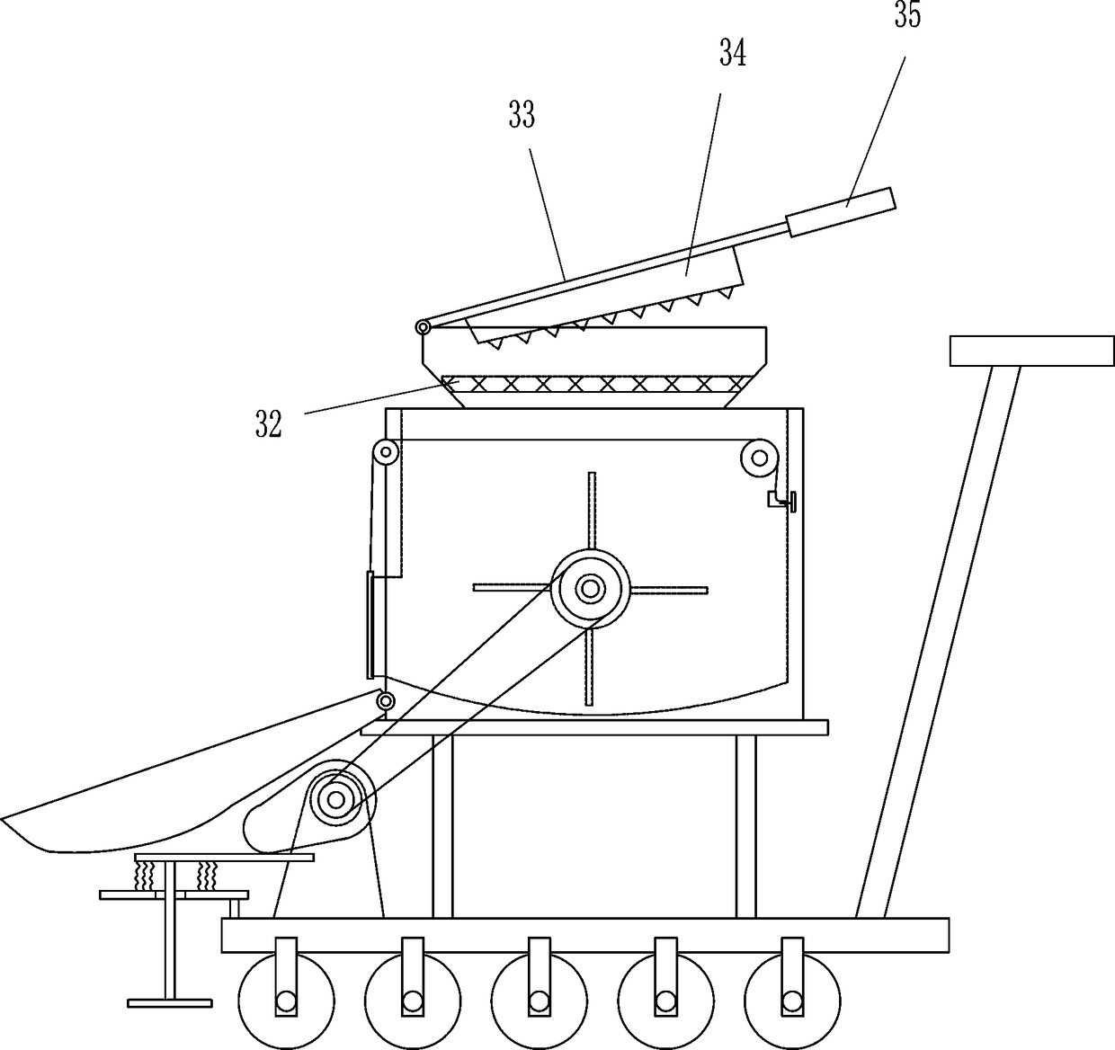
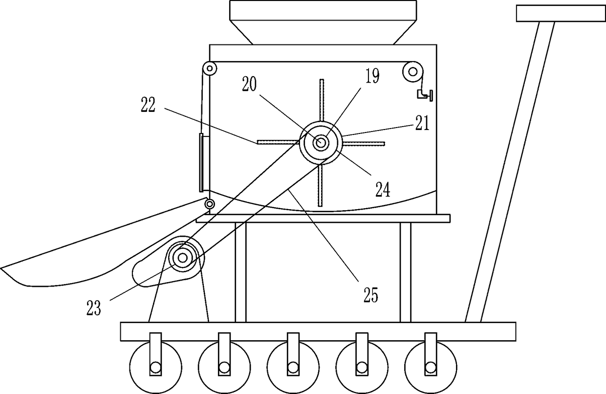
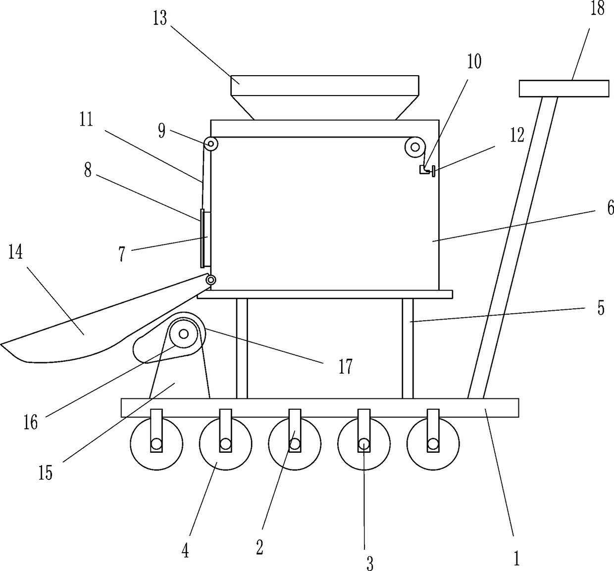
[0024] A road soil filling and compaction device, such as Figure 1-5 As shown, it includes a bottom plate 1, a mounting frame 2, a rotating shaft 3, a roller 4, a mounting seat 5, a box body 6, a discharge pipe 7, a shielding cover 8, a fixed pulley 9, a guide sleeve 10, a draw rope 11, a draw rod 12. Feeding hopper 13, curved bucket 14, fixed seat 15, rotating motor 16, cam 17 and push rod 18. The bottom of the bottom plate 1 is evenly connected to the front and rear sides of the mounting bracket 2, and the corresponding mounting bracket 2 on the front and rear sides Rotating shaft 3 is connected in between, drum 4 is connected to rotating shaft 3, mounting seat 5 is connected to the upper middle of bottom plate 1, box body 6 is connected to the upper side of mounting seat 5, and the discharge pipe is connected to the lower right side of box body 6 7. A cover 8 is slidably connected to the left side of the discharge pipe 7, fixed pulleys 9 are installed on the left and right ...

Embodiment 2

[0026] A road soil filling and compaction device, such as Figure 1-5 As shown, it includes a bottom plate 1, a mounting frame 2, a rotating shaft 3, a roller 4, a mounting seat 5, a box body 6, a discharge pipe 7, a shielding cover 8, a fixed pulley 9, a guide sleeve 10, a draw rope 11, a draw rod 12. Feeding hopper 13, curved bucket 14, fixed seat 15, rotating motor 16, cam 17 and push rod 18. The bottom of the bottom plate 1 is evenly connected to the front and rear sides of the mounting bracket 2, and the corresponding mounting bracket 2 on the front and rear sides Rotating shaft 3 is connected in between, drum 4 is connected to rotating shaft 3, mounting seat 5 is connected to the upper middle of bottom plate 1, box body 6 is connected to the upper side of mounting seat 5, and the discharge pipe is connected to the lower right side of box body 6 7. A cover 8 is slidably connected to the left side of the discharge pipe 7, fixed pulleys 9 are installed on the left and right ...

Embodiment 3

[0029] A road soil filling and compaction device, such as Figure 1-5 As shown, it includes a bottom plate 1, a mounting frame 2, a rotating shaft 3, a roller 4, a mounting seat 5, a box body 6, a discharge pipe 7, a shielding cover 8, a fixed pulley 9, a guide sleeve 10, a draw rope 11, a draw rod 12. Feeding hopper 13, curved bucket 14, fixed seat 15, rotating motor 16, cam 17 and push rod 18. The bottom of the bottom plate 1 is evenly connected to the front and rear sides of the mounting bracket 2, and the corresponding mounting bracket 2 on the front and rear sides Rotating shaft 3 is connected in between, drum 4 is connected to rotating shaft 3, mounting seat 5 is connected to the upper middle of bottom plate 1, box body 6 is connected to the upper side of mounting seat 5, and the discharge pipe is connected to the lower right side of box body 6 7. A cover 8 is slidably connected to the left side of the discharge pipe 7, fixed pulleys 9 are installed on the left and right ...


PUM


Abstract

The invention relates to ra oad soil filling and compacting device, in particular to a road soil filling and compacting device. The technical problem of the invention is to provide a road clay fillingcompaction device capable of compacting the filled clay while transporting the clay for filling, crushing large pieces of clay, and facilitating flexible movement. A road soil filling and compactingdevice comprises a bottom plate, a mounting frame, a rotating shaft, a drum, a mounting seat, a box body, a discharging pipe, a shielding cover, a fixed pulley, a guide sleeve, a drawing rope, a drawing rod, a feeding hopper, etc. A mount bracket is uniformly connected with the front and rear sides of the bottom plate, a rotating shaft is connected with the corresponding mounting brackets of the front and rear sides, and a roller is connected with the rotating shaft. The invention preliminarily crushes the soil through the arranged crushing block, the toggle plate further crushes the soil while pulling out the soil, and the compaction plate can crush the soil laid on the road again while leveling the soil on the road, thereby facilitating the subsequent compaction work.

Description

Technical field [0001] The invention relates to a soil filling and compacting device, in particular to a road soil filling and compacting device. Background technique [0002] In terms of meaning, roads are infrastructures for the passage of various trackless vehicles and pedestrians; according to their use characteristics, they are divided into highways, urban roads, rural roads, factory roads, forestry roads, test roads, competition roads, automobile test roads, and workshop passages. And school roads. Compaction refers to the operation of applying dynamic or static external force to soil or other road construction materials to increase its compactness. [0003] Some roads are inconvenient to pave cement due to their own conditions and usage requirements, such as country roads and certain race roads, which are only composed of soil. The soil is easily eroded by rain, resulting in uneven roads. At the same time, the vehicles passing on the road are too heavy , It will also cause...

Claims


Application Information

Patent Timeline
Patent Type & Authority Applications(China)
IPC IPC(8): E01C23/09
CPCE01C23/0966
Inventor 钟舒悦
Owner 临清市中科建工程有限公司
Why Eureka
Try Eureka