Combined unexploded ammunition energy-gathered destruction device
An unexploded ammunition, combined technology, applied in the field of combined unexploded ammunition shaped energy destroyer, can solve the problems of low safety, poor versatility, and low efficiency, and achieve the effects of less touch, simple structure, and easy operation
- Summary
- Abstract
- Description
- Claims
- Application Information
AI Technical Summary
Problems solved by technology
Method used
Image
Examples
Embodiment 1
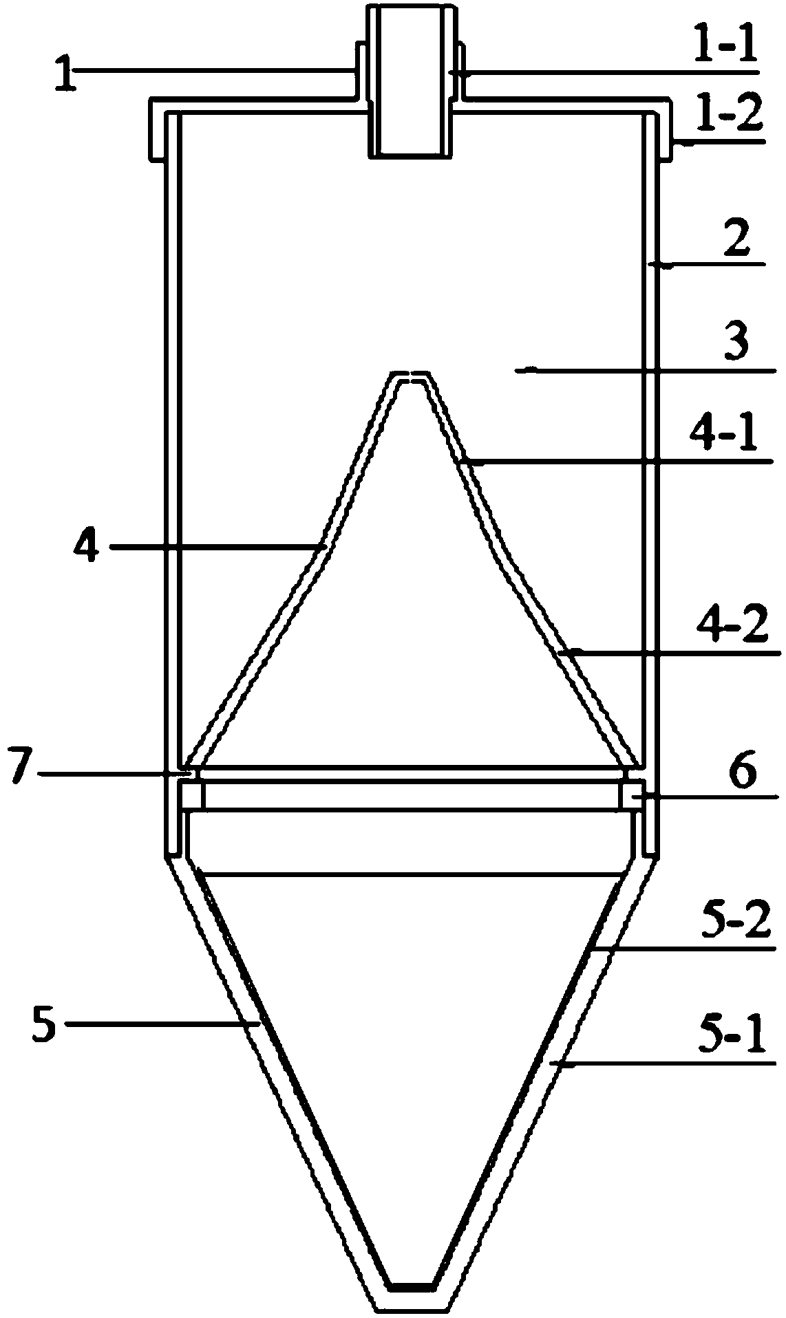
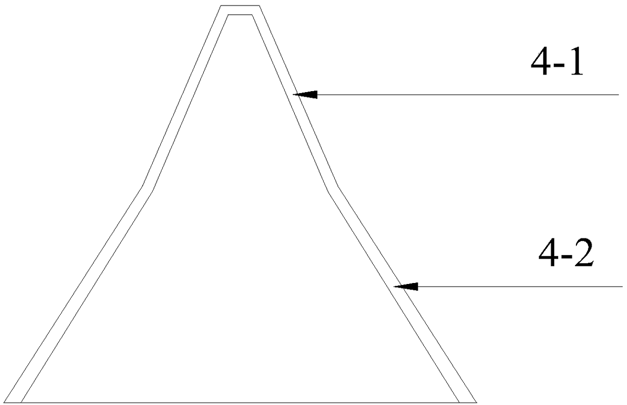
[0039] A combined unexploded ammunition shaped energy destroyer, comprising an end cover 1, a shell 2, a main charge 3, and a metal drug-type cover 4, wherein the detonator seat 11 is arranged in the central hole of the threaded cover 12, and the threaded cover 12 and the The shell 2 is connected by threads, the main charge 3 is located inside the shell 2, the detonator can be inserted into the interior of the main charge 3 to a certain depth through the central hole of the detonator seat 11, and the metal charge cover 4 is constrained by the limit table of the shell 2. And contact with the main charge 3.
[0040] The combined use form of the shaped energy destroyer is: end cover 1﹢shell 2﹢main charge 3﹢metal drug type cover 4.
[0041] The invention can destroy all kinds of unexploded ammunition on land surface and shallow surface on site, and utilizes the direct impact action of high-speed metal jet to penetrate the casing of unexploded ammunition and detonate the internal c...
Embodiment 2
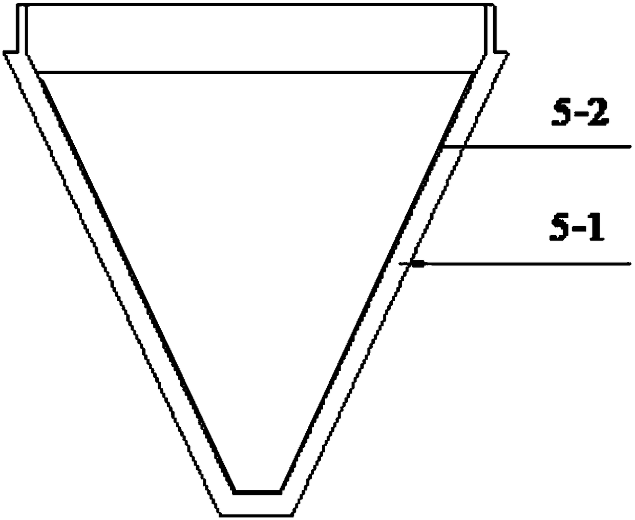
[0043] A combined shaped energy destroyer for unexploded ammunition, comprising an end cover 1, a shell 2, a main charge 3, a metal powder cover 4 and a nose cone 5, wherein the detonator seat 11 is arranged in the central hole of the threaded cover 12 , the threaded cover 12 is threadedly connected with the shell 2, the main charge 3 is located inside the shell 2, the detonator can be inserted into the inside of the main charge 3 through the central hole of the detonator seat 11 to a certain depth, and the metal medicine cover 4 is formed by the shell 2 The limit table constrains the positioning and is in contact with the main charge 3, and the nose cone 5 is screwed into the casing 2 through threads.
[0044] The combined use form of the concentrated energy destroyer is: end cover 1﹢shell 2﹢main powder charge 3﹢metal drug type cover 4﹢head cone 5.
[0045] The present invention can destroy unexploded ammunition on the ground surface with a medium-thickness shell wall on the ...
Embodiment 3
[0047] A combined unexploded ammunition shaped energy destroyer, comprising an end cover 1, a shell 2, a main charge 3, a metal drug cover 4, a nose cone shell 51 and an O-ring 6, wherein the detonator seat 11 is arranged on the thread In the central hole of the cover 12, the threaded cover 12 is threadedly connected with the shell 2, the main charge 3 is located inside the shell 2, and the detonator can be inserted into the interior of the main charge 3 to a certain depth through the central hole of the detonator seat 11. 4. Positioned by the limiting platform of the shell 2 and in contact with the main charge 3, a sealing ring 6 is added to the threaded end of the nose cone shell 51 and then screwed into the shell 2 through threads.
[0048] The combined use form of the concentrated energy destroyer is: end cover 1﹢shell 2﹢main powder charge 3﹢metal powder cover 4﹢cone shell 51﹢sealing ring 6.
[0049] The present invention can realize the destruction operation of the unexpl...
PUM
 Abstract
Description
Claims
Application Information
 - R&D
- Intellectual Property
- Life Sciences
- Materials
- Tech Scout
- Unparalleled Data Quality
- Higher Quality Content
- 60% Fewer Hallucinations
Browse by: Latest US Patents, China's latest patents, Technical Efficacy Thesaurus, Application Domain, Technology Topic, Popular Technical Reports.
© 2025 PatSnap. All rights reserved.Legal|Privacy policy|Modern Slavery Act Transparency Statement|Sitemap|About US| Contact US: help@patsnap.com


