
Sound production device and electronic equipment

A technology for sounding devices and metal casings, which is applied in the direction of electrical components, electromechanical sensors, microphone mouths/microphone accessories, etc., and can solve the problem of the width and wall thickness of the coated tape, the inner wall of the casing that is easy to touch, and the appearance of the sounding device. Poor sound effects and other problems, to achieve the effect of simplifying the installation process, improving acoustic performance, and reliable connection

Active Publication Date: 2020-03-27
GOERTEK INC
View PDF8 Cites 3 Cited by
  • Summary
  • Abstract
  • Description
  • Claims
  • Application Information

AI Technical Summary

Problems solved by technology

[0002] At present, the casing of loudspeaker products is generally formed by integral injection molding of annular washer and plastic. In this structure, due to the limitation of injection molding conditions and in order to ensure the structural strength of the plastic casing, it is usually necessary to set the size of the plastic casing to be large, which will make the coating The tape width and wall thickness are thicker, which will reduce the vibration space of the diaphragm. When the diaphragm vibrates, the diaphragm ring is easy to touch the inner wall of the casing, resulting in poor sound output from the sound generating device.

Method used


Image

  • Sound production device and electronic equipment
  • Sound production device and electronic equipment
  • Sound production device and electronic equipment

Examples


Embodiment Construction

[0027] The following will clearly and completely describe the technical solutions in the embodiments of the present invention with reference to the accompanying drawings in the embodiments of the present invention. Obviously, the described embodiments are only part of the embodiments of the present invention, not all of them. Based on the embodiments of the present invention, all other embodiments obtained by persons of ordinary skill in the art without creative efforts fall within the protection scope of the present invention.

[0028] It should be noted that if there is a directional indication (such as up, down, left, right, front, back...) in the embodiment of the present invention, the directional indication is only used to explain the position in a certain posture (as shown in the accompanying drawing). If the specific posture changes, the directional indication will also change accordingly.

[0029] In addition, if there are descriptions involving "first", "second" and ...


PUM

PropertyMeasurementUnit
Thicknessaaaaaaaaaa

Abstract

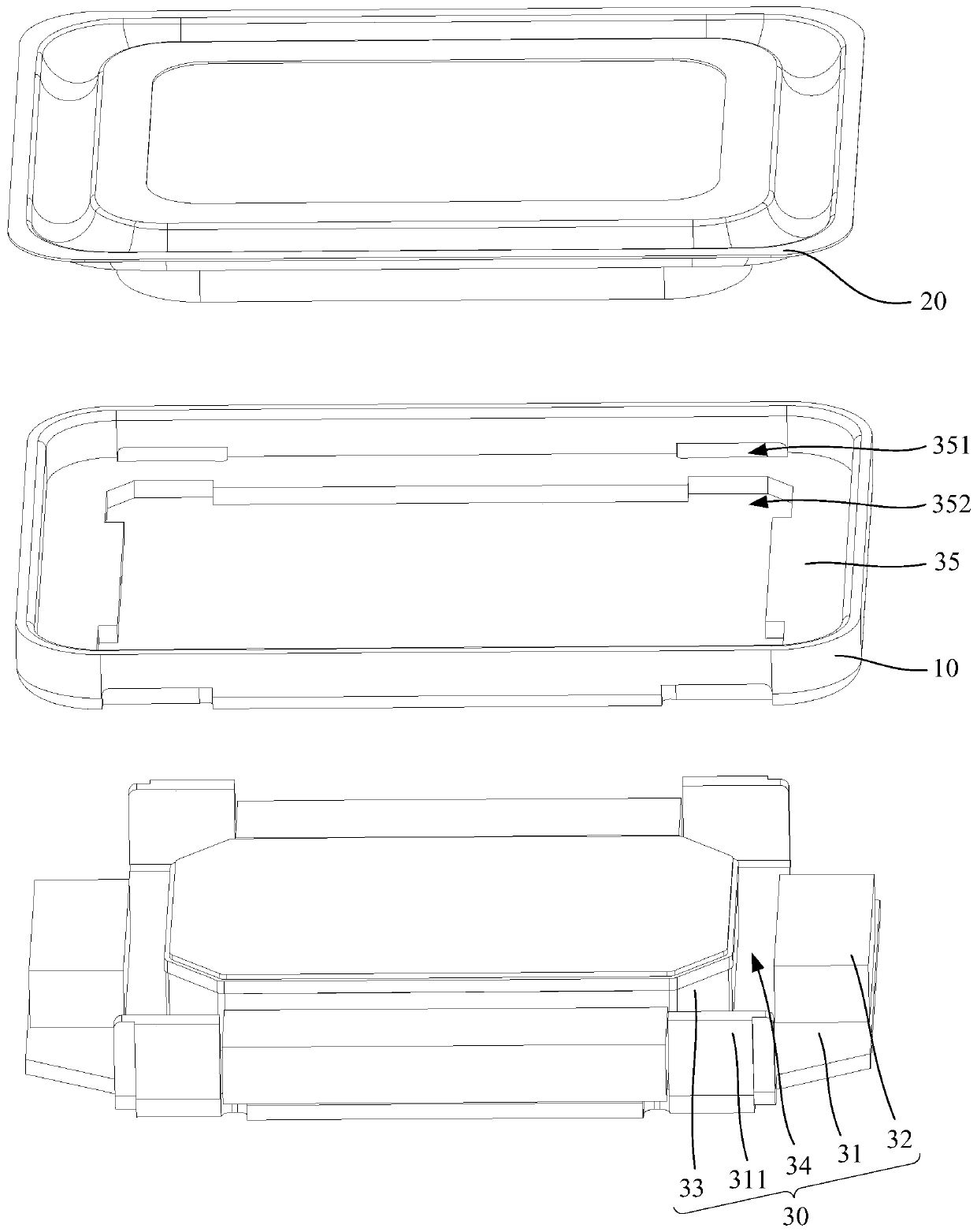
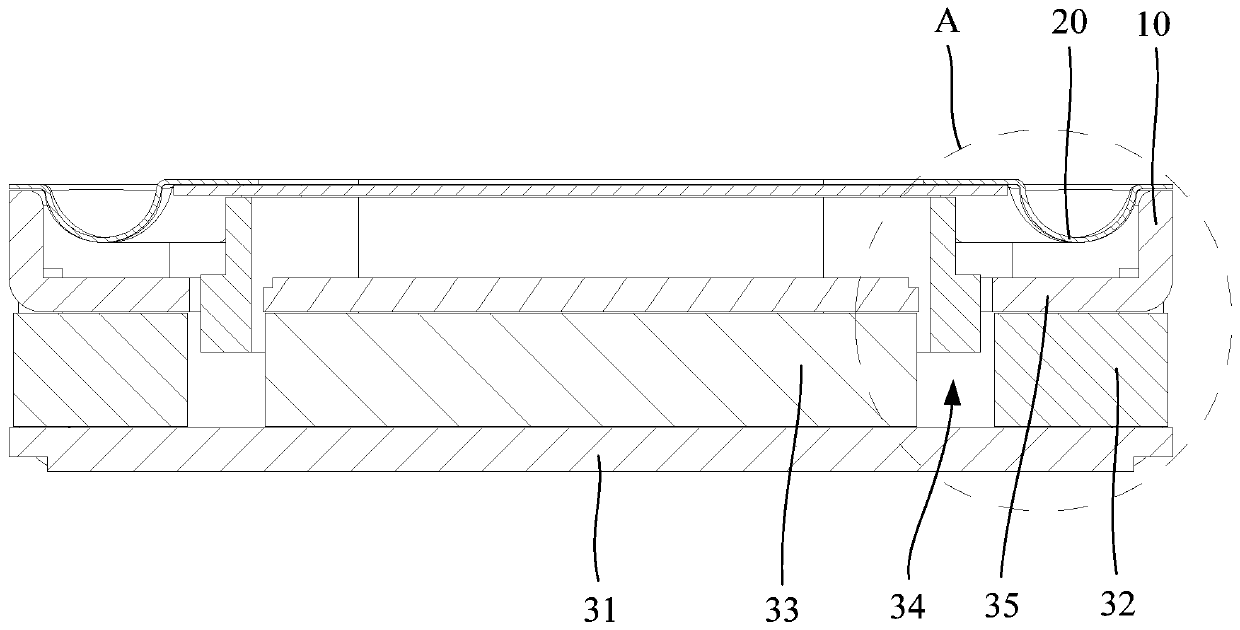
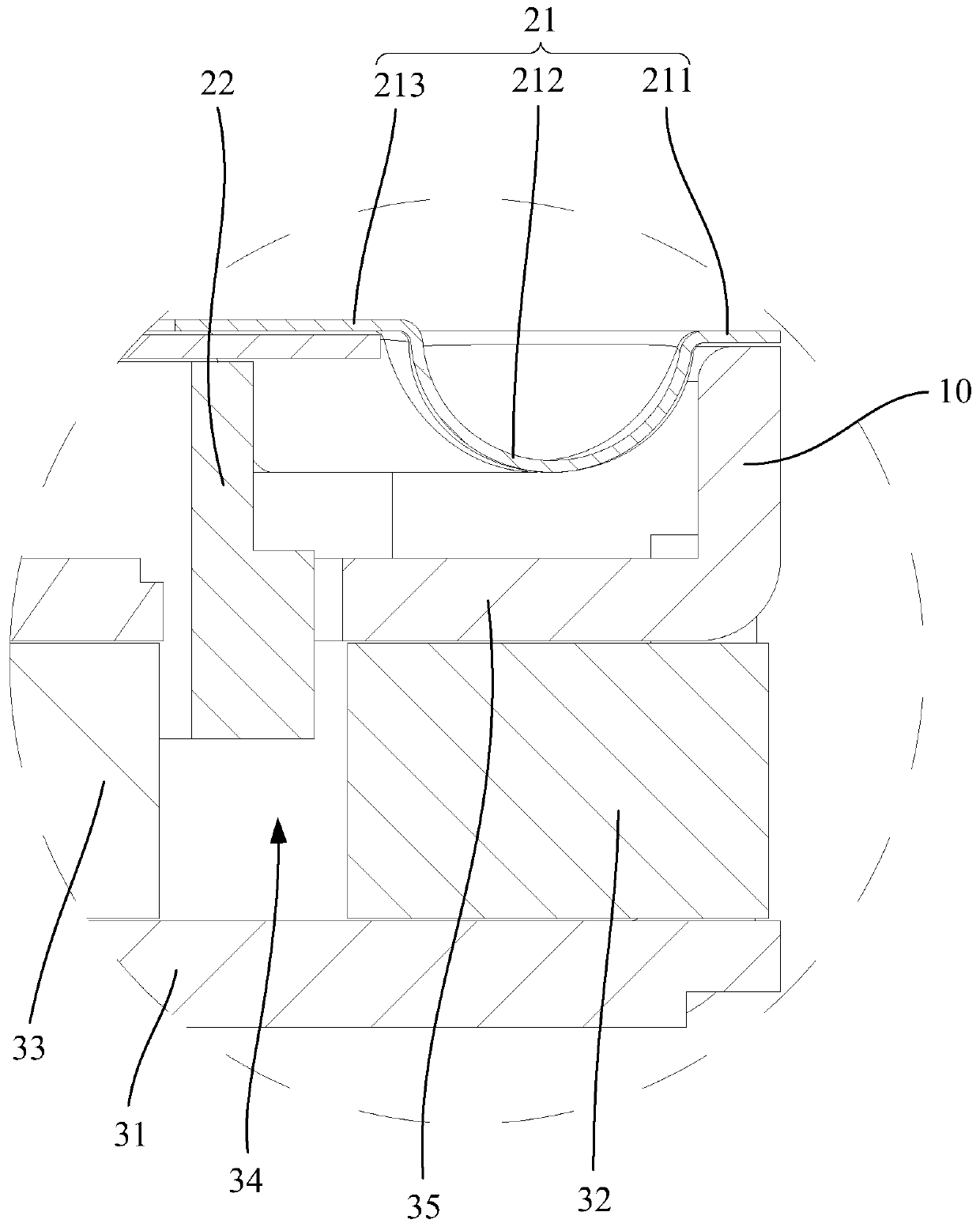
The invention discloses a sound production device and electronic equipment, the sound production device comprises a magnetic circuit system, a vibration system and a metal shell, the magnetic circuitsystem comprises a magnetic conductive yoke, a side magnet arranged on the magnetic conductive yoke and a side magnetic conductive plate arranged at the upper end of the side magnet, and a magnetic gap is formed on the inner side of the side magnet. The vibration system comprises a vibrating diaphragm and a voice coil arranged on the vibrating diaphragm, and at least part of the voice coil extendsinto the magnetic gap. The metal shell is arranged in an annular shape, the vibrating diaphragm is installed at the upper end of the metal shell, the side concentrating flux plate is connected to thelower end of the metal shell, and the metal shell and the side concentrating flux plate are integrally formed in a deep drawing mode. According to the technical scheme, the vibration space of the diaphragm can be increased, and the acoustic performance of the sound production device is improved.

Description

technical field [0001] The invention relates to the technical field of sound energy conversion, in particular to a sound generating device and electronic equipment. Background technique [0002] At present, the casing of loudspeaker products is generally formed by integral injection molding of annular washer and plastic. In this structure, due to the limitation of injection molding conditions and in order to ensure the structural strength of the plastic casing, it is usually necessary to set the size of the plastic casing to be large, which will make the coating The tape width and wall thickness are thicker, which will reduce the vibration space of the diaphragm. When the diaphragm vibrates, the diaphragm ring is easy to touch the inner wall of the housing, resulting in poor sound output from the sound generator. Contents of the invention [0003] The main purpose of the present invention is to provide a sounding device, which aims to increase the vibration space of the di...

Claims


Application Information

Patent Timeline
IPC IPC(8): H04R9/02H04R9/04H04R7/00H04R1/08
CPCH04R9/025H04R9/04H04R7/00H04R1/08
Inventor 崔现丽刘华伟
Owner GOERTEK INC
Learn More